
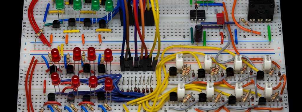
This is the first part of this project describing the prototype.
See part 2 for the final device.
Table of Contents
- Introduction
- My Goals
- From the Idea to a Prototype
- Prototype Demonstration (Video)
- Component List
- Circuit Diagram
- What’s Next?
Introduction
The outmoded sequencer project is a miniature music machine. The sequencer uses a 8×8 matrix which represents one bar with eight beats. On beat one of eight notes can be played. This bar is looped endlessly, but you can change the notes for each beat while the melody is played.
Have a look at the following illustration:
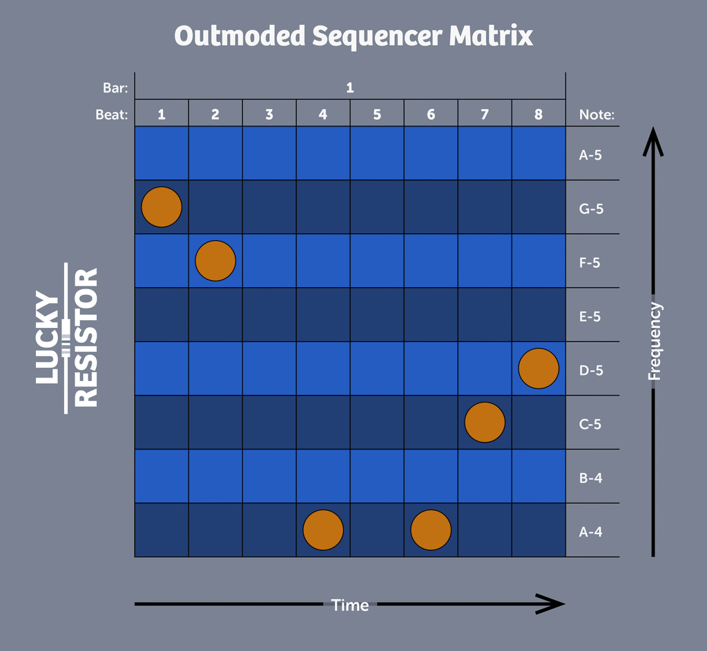
Each beat is played in sequence and starts over at the last one: 1, 2, 3, …, 8, 1, 2, etc. The orange dot on the matrix is the “programmed” note for this beat. For beat 1, there is a dot in the row for the note G-5 which is played in this case. The sequencer will advance to beat 2 and play the note F-5 there. Next it will advance to beat 3, where no note is programmed, so there is no sound played for this beat. The sequencer will advance in this way until it reaches the last beat 8, then it will start over with beat 1.
My Goals
I set some goals for this project, I hope they will help you understand why I came to the design as shown.
- No microcontroller.
- Only outmoded, basic and cheap components.
- As minimalistic as possible.
- Maximize the fun with these limitations.
From the Idea to a Prototype
I tried to realise this kind of sequencer with really cheap and outdated components, as explained in the goals section. They usually lie around unused and this is a nice project to make use of them.
First I setup a basic prototype as shown in the following photo:
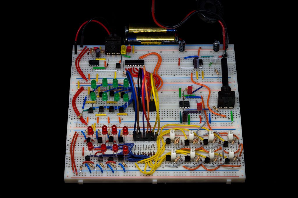
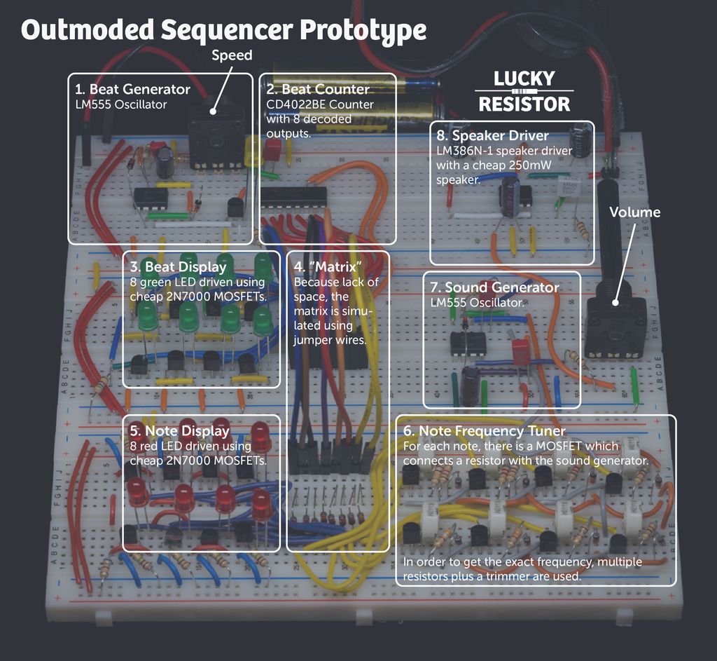
The prototype looks complicated, but actually it isn’t. It is just the amount of components which make it look complicated. The prototype is divided into eight simple parts as shown in the following legend:
Beat Generator
Everything starts with the beat generator. This is a simple oscillator built using the LM555 chip. The circuit diagram for this part is shown below:
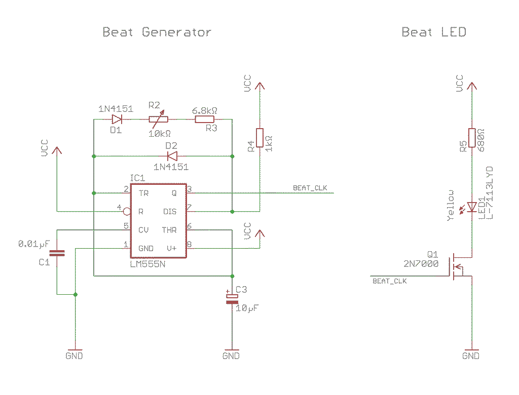
There is nothing special about the LM555 oscillator circuit, except the two diodes D1 and D2. They make sure, C3 is only charged by R4 and discharged by R2+R3. A yellow LED is attached to the resulting signal BEAT_CLK, using a 2N7000 MOSFET. You can attach the LED directly to the signal if you like, because for this LED the MOSFET is not necessary. I choose this design, because all other LEDs are connected in the exact same way.
The speed for the beat can be adjusted with the potentiometer R2. I used the symbol for a variable resistor in this schema to keep things simple. In the actual hardware it is a potentiometer where the middle and of of the other pins are connected to build a variable resistor between zero and 10kΩ.
Beat Counter, Beat Display
To convert the beat into a signal on one of the eight columns of the matrix, the CD4022BE is used. It is a counter with eight decoded outputs. This means, there always one of the eight outputs is in “high” state and all other are in “low” state. The circuit diagram for this part is shown below:
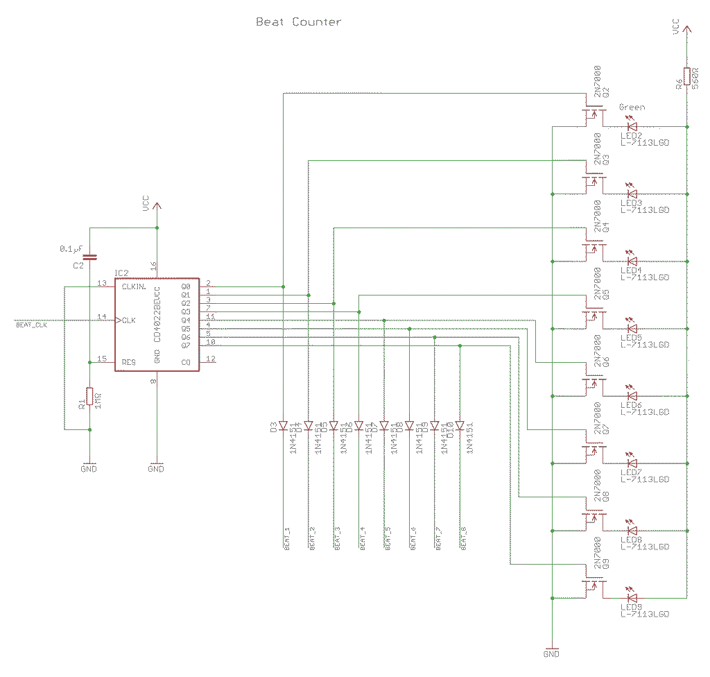
The signal from the previous circuit (BEAT_CLK) is connected to the clock input of the counter (CLK). Reset (RES) is connected to the group with a 1MΩ resistor and to VCC with C2, a 0.1µF capacitor. This will automatically reset the counter, as soon the circuit is powered up. There is the clock inhibit pin (CLKIN.) which is not used and therefore connected to the ground.
Each of the eight outputs is connected to a MOSFET (Q2-Q9) which drives one of the green LEDs (LED2-9). They share one resistor (R6), because there can be only one LED lit up at any point in time. This LEDs are a visual indicator which beat currently is played. The outputs of the counter chip are not meant to drive a LED, the current there is really low. A LED will light up, but very dim.
Finally there are eight diodes which send the signal into the matrix. They are required to prevent any current flowing back into the other outputs if two or more points in the same row of the matrix are connected. Because of the low frequency, almost any diode will do. I use the 1N4151TR, which is not the cheapest you can get (~$0.03), but a very universal one.
The Matrix
In the prototype I could not really build the matrix as it would be in the final device. It would be eight columns and eight rows and at each where they cross, a possibility to connect the row with the column. It is visualised in the following circuit diagram:
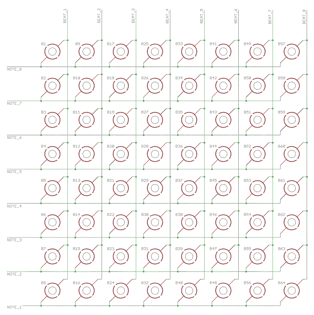
The symbols B1-B64 represent pads, where the “beat” write can be connected with the “tone” wire. There are endless ways how to do this, I will experiment with small magnets and steel balls from a ball bearing.
Note Display and Frequency Tuning
The note display uses eight red LEDs to display the current played note. From the same signal, the frequency tuning part is driven. Here a MOSFET will let the current flow trough different resistors to change the frequency of the oscillator which produces the sound. See the following circuit diagram for all details:
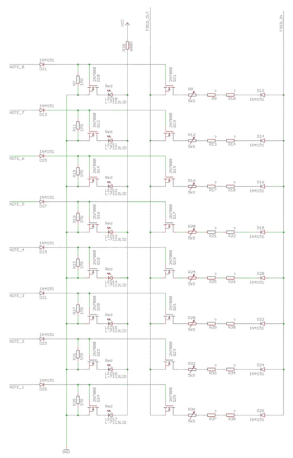
The signal from the matrix goes trough a diode (D11, D13, …, D25) and to the gate of two MOSFETs. There is also a 1MΩ resistor to the ground, to make sure the MOSFETs block while there is no signal on the input. The first MOSFETs (Q10, Q12, …, Q24) drive the red LEDs to display the current note played. The LEDs are all connected to one single resistor (R39), because there should never be more than one LED lit simultaneously.
The second MOSFETs (Q11, Q13, …, Q25) control the frequency of the played note. They connect each a trimmer and one or two resistors and a diode into the sound generator part. There are no concrete values in the schema, because you have to measure and fine tune each tone for yourself. Cheap resistors have 5% or even 10% tolerance, so it really depends on the individual resistor you use which frequency you get.
The best way is to have a look which frequency you need, attach an oscilloscope to the output of the sound generator and play with the resistor values until you get as close as possible to the right frequency. First put the trimmer in the middle position, then try resistors until you get close the the target frequency and finally use the trimmer to tune it exactly.
The following table is showing you the eight tones I selected and the correct frequency of the tones. It also shows you the measured resistance of my prototype, which provides you with a approximate starting point. It is the value for the whole series including the trimmer. So if the value is below 5kΩ, you can omit the resistor completely and just use jumper wire.
| Row | Note | Frequency | Resistance |
|---|---|---|---|
| 8 | A-5 | 880.000Hz | 0.85kΩ |
| 7 | G-5 | 783.991Hz | 2.10kΩ |
| 6 | F-5 | 698.465Hz | 3.53kΩ |
| 5 | E-5 | 659.255Hz | 4.36kΩ |
| 4 | D-5 | 587.330Hz | 6.15kΩ |
| 3 | C-5 | 523.251Hz | 8.19kΩ |
| 2 | B-4 | 493.883Hz | 9.31kΩ |
| 1 | A-4 | 440.000Hz | 11.78kΩ |
For the setup as shown, the diodes (D11, D13, …, D25) are not really required and can be omitted. They are in place to allow the tones be manually played using some push buttons which connect VCC to the point after the diode. The diode prevents cross connections in this case.
Sound Generator
The sound generator is a simple LM555 based oscillator. It uses a different capacitor to generator a higher frequency as the generator for the beat. See the following circuit diagram for all details:
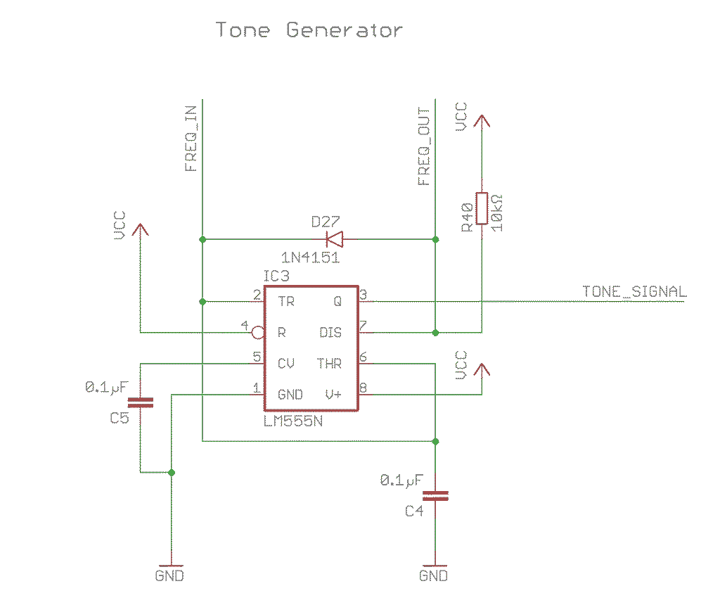
The circuit also uses two diodes, similar to the beat generator. They simplify the frequency tuning, because the frequency is only affected by one single resistance value in one direction.
You can stop here and connect a buzzer to the output of the LM555, to shape the sound into a little bit more pleasant form and drive a speaker, I add a speaker driver.
Speaker Driver
The speaker driver uses the LM386N-1, which was made exactly for this kind of task. Usually it will run at higher voltages, starting from 4.5V, but if you do not expect much, it will also run from 3V. See the following schema for all details:
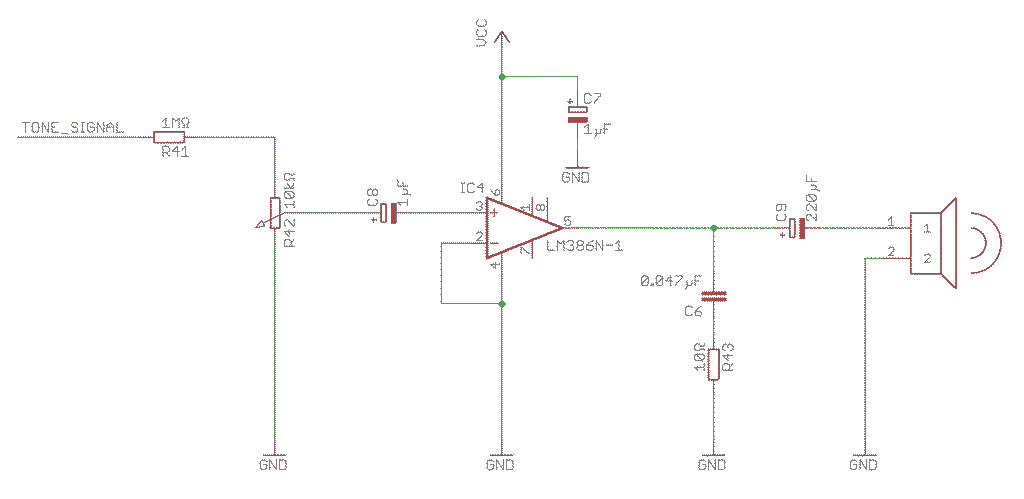
First, the DC signal from the LM555 is attenuated with an 1MΩ resistor (R41), then a potentiometer allow choosing the output volume. The capacitor C8 converts the DC signal into an AC signal, which is fed into the amplifier.
The attached speaker has to be a 8Ω one, minimum 250mW. Make sure the capacitor C9 is large enough, it is required to generate enough current to drive the speaker. Also capacitor C7 is required, as close as possible to the driver chip. If you omit it, it can affect the rest of the circuit.
You can also connect the circuit to any audio interface. In this case, replace R41 with a resistor somewhere around 200kΩ, and connect the audio interface just after capacitor C8. After you attach the audio interface, start with the potentiometer R42 in the lowest position, then slowly turn it until you get in the right range for the audio interface. Usually a common maximum(!) audio interface input voltage is approximate 1.2v (AC), you may want to measure this before you plug the circuit it into your expensive device.
Prototype Demonstration
The following video demonstrates the prototype in action. You can see how the sequencer works in different configurations. I also added the matrix, how the sequencer is programmed. Please note, I did not choose the examples for nice melodies, I just put some random notes in the matrix to demonstrate the circuit.
Here a music composition, created using the outmoded sequencer as shown in this project:
[soundcloud url=“https://api.soundcloud.com/tracks/278944834” params=“auto_play=false&hide_related=false&show_comments=true&show_user=true&show_reposts=false&visual=true” width=“100%” height=“450” iframe=“true” /]
Component List
The following table contains all required components you need to build your own outmoded sequencer. There is a column “Alternative”, were you find if there is an alternative to the component or how important the correct value of the component is. Be aware, if you use alternatives, you will have to make own modifications to the circuits and probably adjust other values to make everything work.
| Name | Value | Alternative | Usage |
|---|---|---|---|
| 9×Resistor | 1MΩ | 100kΩ-1MΩ | Resistors R7, R11, …, R35 + R1 used as pull-down resistors. Lower values lead to more quiescent current. |
| 1×Resistor | 1MΩ | 600kΩ-2MΩ | Resistor R41 used to attenuate the signal from the LM555. Lower values lead to clipping of the sound if you pull the potentiometer to the maximum. |
| 1×Resistor | 6.8kΩ | 4kΩ-10kΩ | Resistor R3 used to set the base of the beat frequency. |
| 1×Resistor | 1kΩ | 800Ω-4kΩ | Resistor R4 used to set the beat frequency. |
| 2×Resistor | 680Ω | – | Resistor R5 is the correct resistor in front of the L-7113LYD and L-7113LID LEDs, you may need another one. |
| 1×Resistor | 560Ω | – | Resistor R6 is the correct resistor in front of the L-7113LGD LEDs, you may need another one. |
| 1×Resistor | 10Ω | – | Resistor R43 is used with capacitor C6 to create some kind of high-pass filter. |
| 1×Resistor | 10kΩ | – | Resistor R40 defines the frequency of the tone generator, if you change this resistor you have to change all other resistors which define the frequency. |
| ?×Resistor | ? | 100Ω-10kΩ | You need various resistors for R9, R13, …, R37 to tune in the right frequency. See the table above for approximate required values (-2.5kΩ!). for approximate required values (-2.5kΩ!). |
| 8×Trimmer | 5kΩ | 1kΩ-10kΩ | The trimmer are used to tune the frequency. Lower ones (1kΩ) can be used, but then you have to use a more accurate resistor to tune the frequency. Higher ones will do as well, but then it is not easily possible to tune the frequency accurately. |
| 2×Potentiometer | 10kΩ | 10kΩ-50kΩ | The two potentiometer are used to control the volume of the sound and the speed of the beat. |
| 4×Capacitor | 0.1µF | – | These capacitors C1, C4 and C5 define the timing of the oscillators and C2 is used to create the reset signal. |
| 1×Capacitor | 10µF | – | C3 defines the frequency of the beat oscillator, if you change this capacitor this frequency changes, which requires different resistors and a different potentiometer to change the frequency. |
| 2×Capacitor | 1µF | 1µF-10µF | C8 is used to convert the DC sound signal into an AC signal, C7 stabilises the power in front of the amplifier. |
| 1×Capacitor | 220µF | 100µF-470µF | C9 is used to generate the current to drive the speaker. |
| 27×Diode | 1N4151 | Similar | The diodes are used for various tasks, none is critical. Any similar diode will do. |
| 17×LEDs | L-7113L?D | Similar | These high efficiency LED only need 2mA to light up very bright. Any similar LED will do. |
| 25×MOSFETs | 2N7000 | Similar | These MOSFETs are used as simple switches, any similar ones will do. |
| 2×LM555N | LM555N | Similar | The oscillators are used to generate the beat and the sound. |
| 1×CD4022BE | CD4022BE | Similar | This counter is used to select the correct column for the beat. Any similar counter IC will do. |
| 1×LM555N | LM555N | Similar | The amplifier is used to drive a speaker from the sound signal and improve the tone removing a bit of the hard edge. You can completely omit the driver part and connect a buzzer to the output of the LM555N, or just implement it up to the input of the driver chip - so you can connect it to any audio device. If you have another speaker driver, this will do as well. |
| 1×Speaker | 8Ω | Similar | For the sound output you need a speaker, but you can omit this and find a own solution. |
Naturally you need other equipment to build the circuit. You will need wire and some board or platform to create the matrix and to build the circuit on it. You also need batteries, and a battery holder to power the device. You may want two knobs for the potentiometer, etc.
Circuit Diagram
Here a link to a PDF with the complete circuit diagram. The PDF is the latest version of the project and the component numbers do not match the ones shown on the diagrams above.
Outmoded Sequencer v1.0 Circuit Diagrams
Here the detailed part list of all components I will use in the final device. This component list matches the circuit diagram in this PDF.
| Part | Value | Type | Manufacturer |
|---|---|---|---|
| B1-B64 | - | Custom Connector | - |
| C1 | 0.01µF | - | Wima |
| C2 | 0.1µF | C320C104K5R5TA7301 | Kemet |
| C3 | 0.1µF | C320C104K5R5TA7301 | Kemet |
| C4 | 10µF | ECA1CM100 | Panasonic |
| C5 | 0.1µF | C320C104K5R5TA7301 | Kemet |
| C6 | 1µF | SKR010M1HD11-U | Jamicon |
| C7 | 0.1µF | C320C104K5R5TA7301 | Kemet |
| C8 | 1µF | SKR010M1HD11-U | Jamicon |
| C9 | 0.1µF | C320C104K5R5TA7301 | Kemet |
| C10 | 0.047µF | - | Wima |
| C11 | 220µF | 16ZLH220MT16.3X11 | Rubycon |
| D1-D27 | - | 1N4151 | Philips Semiconductors |
| IC1 | - | LMC555CN | Texas Instruments |
| IC2 | - | CD4022BE | Texas Instruments |
| IC3 | - | LMC555CN | Texas Instruments |
| IC4 | - | LM386N-4/NOPB | Texas Instruments |
| LED1 | - | L-7113LYD | Kingbright |
| LED2-LED9 | - | L-7113LGD | Kingbright |
| LED10-LED17 | - | L-7113LID | Kingbright |
| LINEOUT | - | FCR1295 | Cliff |
| PWR | - | - | - |
| Q1-Q25 | 2N7000 | 2N7000 | Diotec |
| R1 | 1MΩ | CFR-25RD14S | YAGEO |
| R2 | 10kΩ | PC16SH10IP06-103A2020–TA | Piher |
| R3 | 6.8kΩ | CFR-25RD14S | YAGEO |
| R4 | 1kΩ | CFR-25RD14S | YAGEO |
| R5 | 680Ω | CFR-25RD14S | YAGEO |
| R6 | 560Ω | CFR-25RD14S | YAGEO |
| R7-R14 | 1MΩ | CFR-25RD14S | YAGEO |
| R15 | 680Ω | CFR-25RD14S | YAGEO |
| R16-R23 | 5kΩ | M64Y502KB40 | Vishay |
| R24 | ? | - | - |
| R25 | ? | - | - |
| R26 | ? | - | - |
| R27 | ? | - | - |
| R28 | 10kΩ | CFR-25RD14S | - |
| R29 | 10kΩ | PC16SH10IP06-103A2020–TA | Piher |
| R30 | 10kΩ | CFR-25RD14S | YAGEO |
| R31 | 10Ω | CFR-25RD14S | YAGEO |
| R32 | 1MΩ | CFR-25RD14S | YAGEO |
| R33 | 1kΩ | CFR-25RD14S | YAGEO |
| R34 | 39kΩ | CFR-25RD14S | YAGEO |
| SPK1 | K 36 WP 8 OHM | Vision | |
| SW1 | SS12SDP2 | NKK |
I used some old parts where I do not know the exact part number. As soon the final device is done, I will fill this missing information.
What’s Next?
This is the end of part one of this project. See part 2 for the final device.