published: August 26, 2024 —
last modified: October 23, 2025
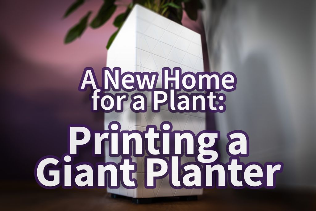
I recently completed and shared the model files for a giant 3D-printed planter, a project that has truly pushed the boundaries of what’s possible with 3D printing. Standing at an impressive 70 cm (around 28 inches) tall and 35 cm (14 inches) wide at the top, this planter is a substantial piece, especially for a 3D-printed object.
In this post, I’d like to take you through the entire journey of designing and creating this unique planter. I’ll delve into the thought process behind the design, discuss the specific features I included, and explain the challenges I encountered along the way. My hope is that this detailed account will not only offer insights into designing large-scale 3D-printed objects but also shed light on some of the less obvious design decisions that were made to accommodate both aesthetic and functional needs.
The journey to creating this giant planter began with my Ctenanthe setosa, a resilient plant native to Brazil. This plant is characterized by its long stems adorned with large, strikingly striped green and white leaves. It’s a hardy species, thriving in low light while constantly adjusting its leaves to capture optimal sunlight.
Over the years, I’ve had to replant my Ctenanthe multiple times, each time moving it into a larger pot. During these replanting sessions, I consistently noticed something intriguing—the plant’s roots grew remarkably deep, often becoming tangled at the bottom of the pot. This behavior suggested that the plant prefers to extend its roots downward, likely mimicking its natural environment where it grows beneath the shade of towering trees, seeking water from deep within the soil.
When my Ctenanthe outgrew its pot once again, I began searching for a tall, narrow planter that would accommodate its deep-rooting habit. Surprisingly, I found that while many planters boast impressive heights of 70 cm or more, their actual containers are disappointingly shallow, primarily serving decorative purposes. This design makes sense for most plants, but it was far from ideal for my Ctenanthe.
I realized that a deeper container would pose challenges, particularly concerning water management and substrate layering. Yet, I was undeterred—after all, no one would fill such a tall planter with regular soil alone.
Faced with the lack of suitable commercial options, I decided to take matters into my own hands. If no one was making the planter I needed, I would design and 3D print it myself.
Design Inspiration and Goals
The Search for the Perfect Shape
Once I decided to design and 3D print a custom planter, I started paying close attention to planters wherever I went, searching for one that would inspire the right shape and size. After examining countless options, I found myself drawn to rectangular planters with a 2:1 ratio. This shape struck the perfect balance between elegance and practicality, especially those with a subtle curve rather than sharp, straight lines. Additionally, I knew that the planter had to be white to seamlessly blend into its surroundings.
Defining the Design Goals
My primary goal was to print the entire planter—both the outer shell and the inner container—using my Prusa XL. The design needed to maximize the available height for the inner container, allowing plenty of room for the plant’s deep roots.
I was also committed to maintaining the raw, unprocessed look of 3D printing. I wanted the shell to proudly showcase its 3D-printed origins, with no post-processing or painting. The challenge was to achieve a level of print quality so high that the planter would appear flawless from a distance, yet reveal its printed nature upon closer inspection.
Given the Ctenanthe’s sensitivity to overwatering, managing excess water was a crucial consideration. In smaller planters, this isn’t much of an issue, but with a larger planter, draining excess water can be a hassle. To address this, I decided to incorporate an access tube that would serve a dual purpose: it could house a sensor to detect excess water and also be used to pump out the water when necessary.
Replanting would inevitably be required at some point, so I designed the inner container to be removable. With the expected weight of around 25kg, the container needed handles or grips strong enough to allow it to be safely lifted out of the shell.
Another challenge was the tendency of the plant’s long stems to bend. While I hoped that allowing the roots to grow deeper would help, I wanted to be prepared. To that end, the container includes holes for plant stakes, providing support if the problem persisted.
Lastly, I aimed to design the planter in a way that it could be easily disassembled—for replanting, cleaning, or upgrading individual parts. I also added a few extension points to allow for the future attachment of additional elements without needing to reprint entire sections.
Research
Before diving into the design of this large planter, I knew I needed to thoroughly understand the challenges and limitations associated with 3D printing at such a scale. My engineering background has taught me that a successful design begins with a deep understanding of the production method, including its potential problems and constraints.
To gain the necessary experience, I embarked on a series of smaller projects focused on large prints. Rather than purchasing off-the-shelf containers, tools, and replacement parts, I decided to design and print them myself. One such project was a 41 cm long replacement compartment for a broken fridge, which served as an excellent test for my design and printing techniques.
Overcoming Warping and Bulging
One of the most significant issues with large-scale 3D printing, especially when using filaments like PETG, is warping. This problem is already challenging with smaller prints, but it becomes exponentially more difficult with larger objects. As the printed filament cools, it contracts, creating forces strong enough to, in extreme cases, lift the metal sheet from the printer bed if left unchecked.
Another common issue with large prints is wall bulging. This occurs when the contraction forces of the cooling filament cause the walls to bend outward, especially if the walls lack sufficient support. This isn’t just a cosmetic problem—it can also increase the layer height, leading to poor layer adhesion and compromising the structural integrity of the print.
Fortunately, there are well-established solutions to these problems. One approach is to incorporate bends and curves into the design. By ensuring that the printed filament lines don’t run in long, straight paths, you can significantly reduce the impact of contraction forces. Additionally, adding ribs or profiles to the walls can provide the necessary support to prevent bulging and twisting, keeping the walls straight and maintaining the print’s structural integrity.
Through my experiments, I discovered an unexpected issue when printing large but thin parts on the Prusa XL. The contraction forces in the filament lines could sometimes cause slight bending of the printer bed itself, resulting in squished layers. This was a new challenge that I hadn’t encountered before, requiring further adjustments to the print setup and design.
Finding the Best Filament
Another critical aspect of my research was finding the best white PETG filament for the planter. White filaments are notoriously difficult to get right, especially when compared to other colors. They often present unique challenges in the printing process, which can be frustrating when working on large prints.
Although I’m not entirely sure of the exact reasons behind these difficulties, I suspect it has to do with the additives used to achieve the opaque white color, such as titanium dioxide or zinc oxide. These materials might make the filament more brittle, and the additional additives required to counteract this brittleness could introduce other side effects, complicating the printing process.
To identify the best filament, I conducted extensive tests, printing numerous large objects in a wide range of white PETG filaments from various manufacturers. I tested brands like 3DJake, Extrudr, FormFutura, Fillamentum, and Fiberlogy. After a lot of trial and error, I found that Fiberlogy’s Easy PET-G was the best choice for my purposes, offering a good balance between print quality and ease of use.
Designing the Shell
Tackling a large project like this can be daunting, so it’s crucial to begin with a solid plan. Breaking the project down into smaller, manageable parts and tasks not only makes the work more approachable but also helps maintain focus on the bigger picture. Defining these steps in advance minimizes the risk of getting lost in the details, ensuring that each part of the project contributes to the overall design.
Creating the Main Shape
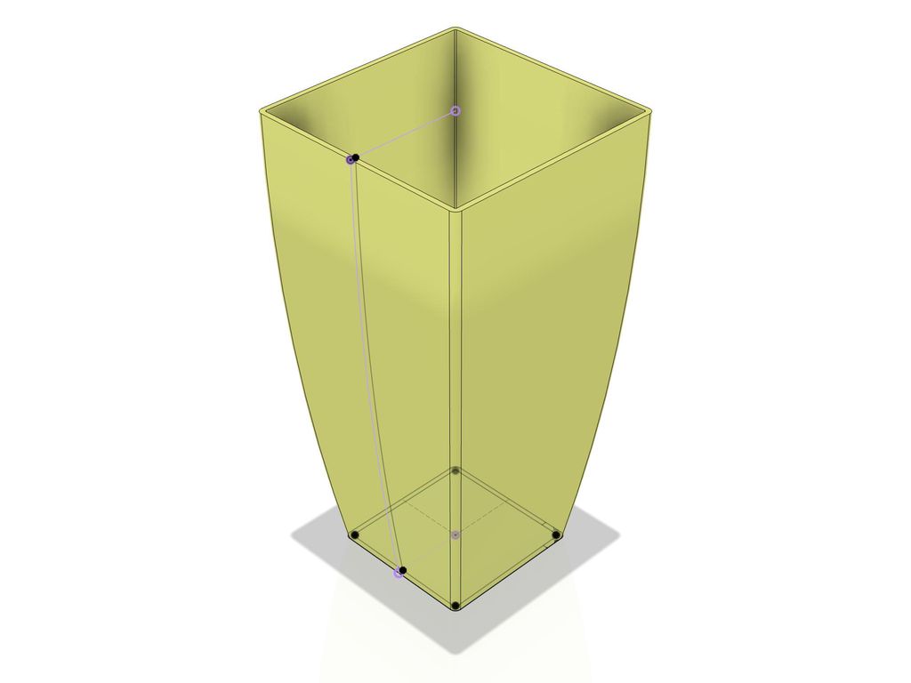
I began by designing the main shape of the outer shell of the planter. Knowing I wanted a 2:1 ratio and considering the space constraints of the Prusa XL printer bed, I settled on a side length of 35 cm. This size allowed for a 5 mm clearance around the object on the printer bed. From this side length, the height of the planter naturally followed, resulting in a 70 cm tall structure.
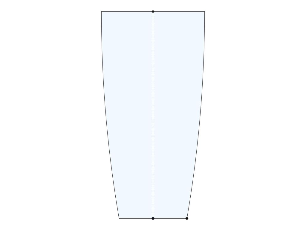
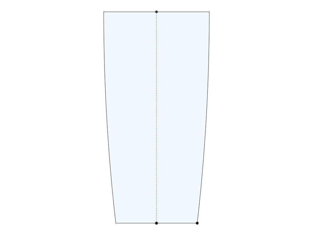
I noticed that planters with a sense of elegance often had a slightly smaller bottom area compared to the top. After analyzing photos of planters I admired, I realized that a ratio of approximately 0.65 between the bottom and top rims was common. I initially experimented with a bottom width of 23 cm, but this only worked well when the top rim already had an angled design.
However, once I introduced the gentle curve I envisioned—where the side wall begins at a 90º angle from the top rim—the 23 cm bottom width felt too narrow. To achieve a visually balanced shape, I adjusted the bottom width to 27 cm, which gave the planter a more harmonious appearance.
Constructing the Walls with Perfect Corners
With the main shape established, I turned my attention to the side walls of the shell. Based on my prior experiments, I decided on 4 mm thick walls. When printed with a 0.4 mm nozzle, using two perimeters and a 10-15% infill with a gyroid pattern, this thickness creates a structure that is both lightweight and strong.
A critical aspect of 3D printing thin walls is ensuring that the wall thickness is consistent at every point on a horizontal plane for each layer of the print. This uniformity is key to achieving a smooth and even surface on the outside of the print.
Unfortunately, the standard shell command in most CAD programs doesn’t achieve this goal. While the walls may have consistent thickness overall, the thickness on a horizontal plane can vary depending on the wall angle.
This principle also applies to the rounded corners. I chose a 10 mm radius for the outer corners, which provided a smooth transition while still maintaining the planter’s rectangular form. This subtle curve adds to the planter’s visual appeal, creating a distinctive line that complements its large size.
After creating the plain side walls for the planter, I went thinking about the outside pattern.
Adding a Functional Pattern
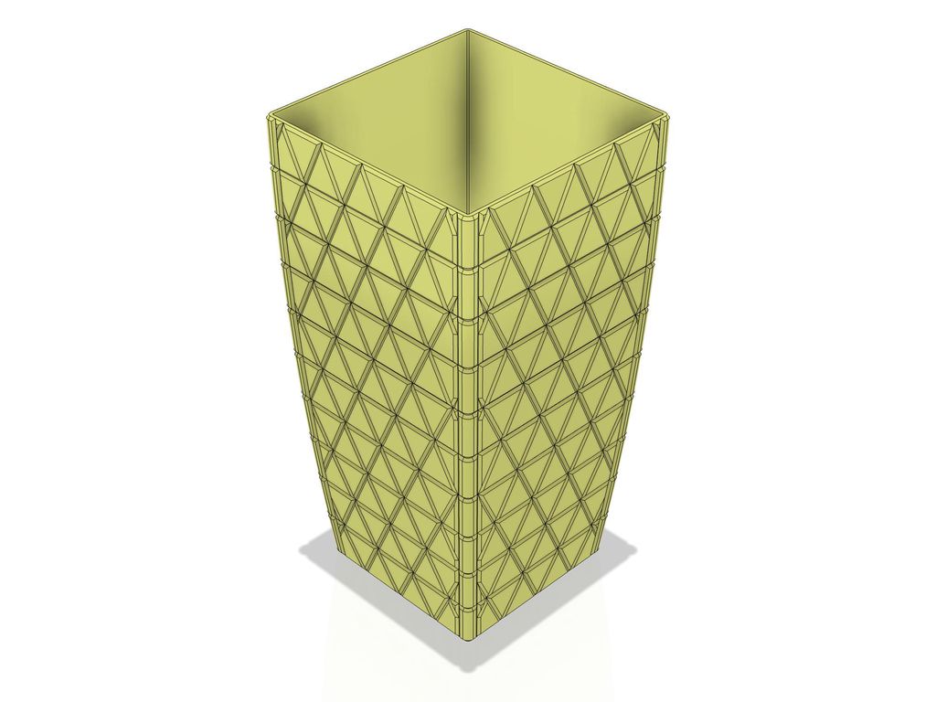
Given that the planter couldn’t be printed in one piece and would require at least two or more separate prints, I realized that a plain exterior wouldn’t be practical. Even the slightest misalignment during assembly would be glaringly obvious. Carpenters often face a similar issue and use a technique called a shadow gap to hide imperfections—a small groove or visual break that masks inconsistencies.
Beyond this aesthetic consideration, there was also a technical challenge to address. Printing a straight filament line over a span of more than 30 cm would inevitably lead to warping due to contraction forces. To mitigate this, I needed to incorporate direction changes in the filament lines to compensate for these forces.
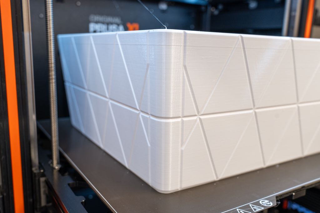
After some experimentation, I found that a geometric triangle pattern not only enhanced the planter’s elegant curved shape but also provided the necessary shadow gaps to conceal any alignment issues. This pattern also introduced the required direction changes along the planter’s vertical height, effectively reducing the risk of warping.
I considered two options: narrow triangles or equilateral triangles that form hexagons. After testing both, I found the equilateral triangles more visually appealing. The side length of these triangles was determined by the number of vertical divisions I planned to create. I settled on nine divisions, which resulted in ten elements and provided a convenient split point in the middle of the shell.
While the horizontal lines of the pattern looked great as they wrapped around the planter and provided the necessary visual breaks, the diagonal lines forming the triangles posed a challenge at the corners. To resolve this, I added a groove that runs parallel to the curve of the corner, effectively solving the issue with the diagonal lines and highlighting the planter’s curved edges.
For the pattern groove’s shape, I cut a triangle with a 110º angle from the outer shell, extending one-third of the wall thickness deep. A 90º angle wouldn’t have worked well because, while it would create a 45º overhang at the top (where the wall is almost straight), the wall is angled at 6.8º at the bottom, leading to a 38.2º overhang. To maintain the best possible print quality, I prefer to keep overhangs within a conservative 45º limit. The 110º cut results in a 55º overhang at the top and a 48.2º overhang at the bottom, both of which are within acceptable limits.
Ribs for Stability and Contraction Compensation
On the outer side of the shell, the patterned triangles effectively prevent any straight filament lines from exceeding the critical length. If contraction occurs, the small triangles created by the diagonal lines act as buffers, absorbing the forces and preventing warping.
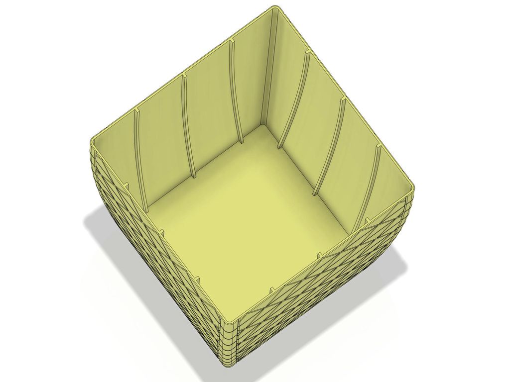
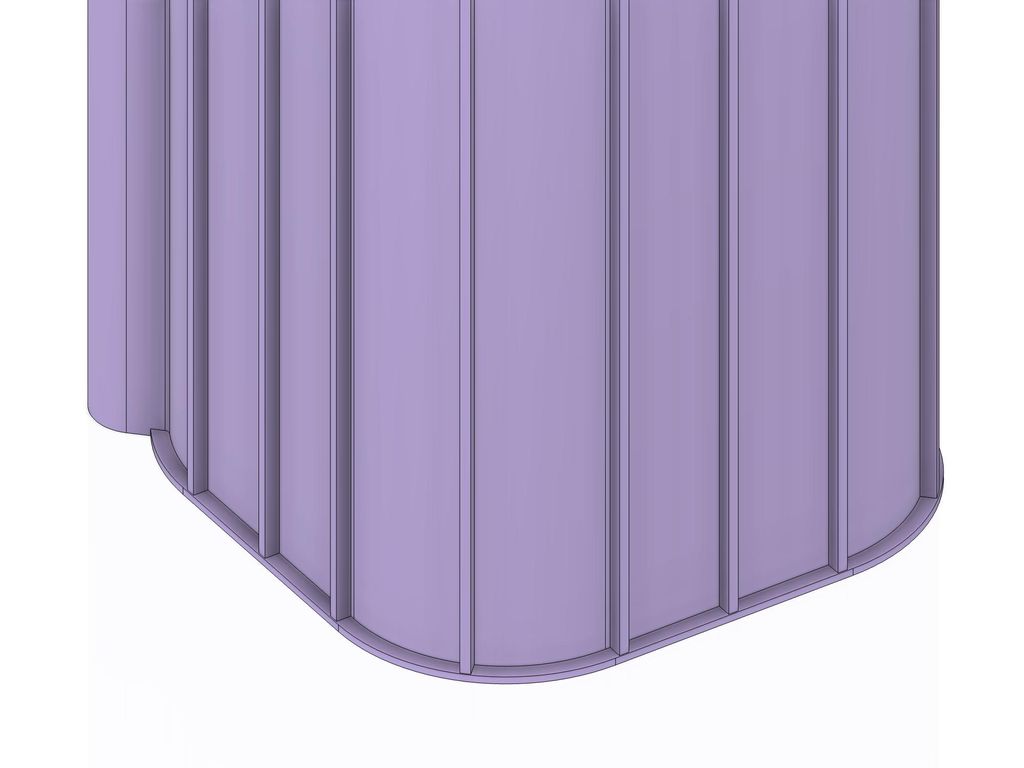
However, on the inside of the shell, the filament lines can easily exceed 25 cm in length, making them more susceptible to contraction-related issues. To address this, I added three vertical ribs on each side of the shell, extending from the bottom to the top rim. These ribs serve a dual purpose: they enhance the structural stability of the walls and, like the grooves on the outside, help to compensate for contraction forces.
When printing hollow walls, as I did for this project, you can often get away with straight filament lines even when they exceed 30 cm, as the infill pattern acts as a flexible buffer, preventing most bulging and warping. Nonetheless, the added ribs are crucial for providing additional stability and stiffness, especially when printing with softer materials like PETG. Also, the type of infill greatly impacts the effectiveness of this buffering. Here, the gyroid pattern is your best choice, because it effectively nulls the contraction forces with all the printed curves.
For the top rim part of the inner container, I decided to omit the ribs entirely. The thick rim and angled wall design provided sufficient stability to prevent most warping. Additionally, I planned to print the inner container with Easy PETG Abyss, which is more forgiving than the white variant and less prone to issues. Yet, this only works with a slow and hollow print, using the gyroid infill pattern.
Tension Release Grooves at the Bottom
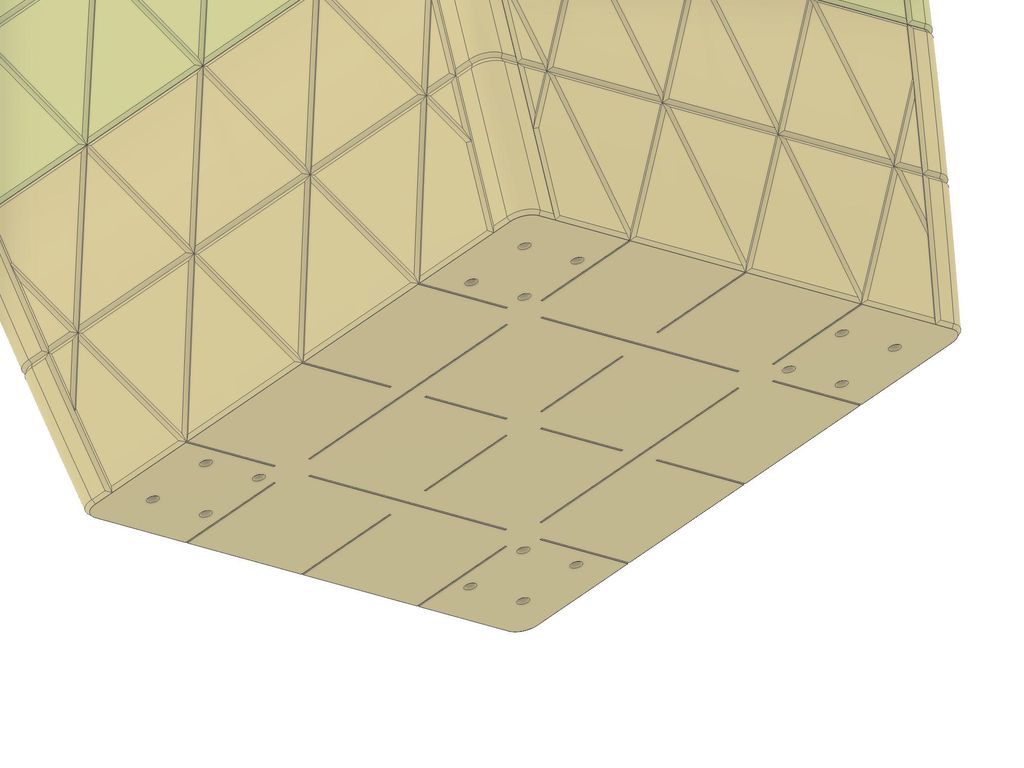
After splitting the shell into two parts, I focused on refining the lower half, like the holes for the threaded inserts to attach feet or rollers to the base. One of the key features I added were the small grooves at the bottom of the shell, which serve a similar purpose as the direction changes created by the side pattern.
When printing the first solid layers, the filament is laid down in long, continuous lines, all oriented in the same direction. Although the heated printer bed helps to prevent immediate contraction by keeping the material warm, the bed temperature of around 80ºC is just barely above the glass transition temperature of PETG. This temperature isn’t quite enough to fully relieve the tension in these regions.
If you’ve worked with PETG before, you might have experienced the snapping sound that occurs when PETG parts release from the printer bed as it cools down. This noise is the result of delayed contraction at the bottom of the print. While this isn’t typically an issue for smaller prints, it can lead to significant bulging in large, uniform areas as the material contracts unevenly.
The tension release grooves I added at the bottom help prevent this issue. These grooves break up the long, uniform filament lines, preventing too much tension from building up in any one area. For this planter, the grooves interrupt the straight perimeter lines and most of the diagonal lines in the solid infill, dividing them into shorter segments. As the bottom cools and contracts, these smaller segments allow the forces to equalize across the entire surface, reducing the risk of bulging.
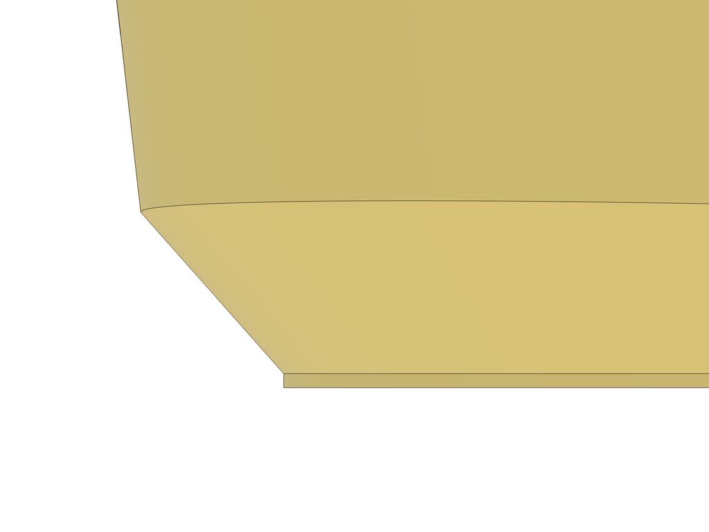
Straight Base Before the First Overhang
If you examine the first overhang near the bottom of the planter, you’ll notice a small, straight base before the transition into the overhang, which is part of the side pattern of the shell. Although this base is quite subtle at just 0.15 mm in height and doesn’t have a significant impact on this particular planter, it’s an important detail worth explaining.
Technically, it’s possible to start a print directly with an overhang, but this initial overhang often lacks the precision that similar features have when printed at higher layers. There are several reasons for this. First, filament cooling is less efficient close to the heated printer bed. Additionally, the printer is still compensating for small height irregularities at this level.
To improve the quality of the first overhang, it’s beneficial to include a small base before the overhang begins. Ideally, this base should be at least three layers high, which allows the overhang to be printed in a region where the height compensation has already been largely addressed, and the distance from the printer bed is sufficient for effective filament cooling.
Obviously, this makes only sense if the bottom of the printed part stays at this orientation. If this first overhang is part of a chamfer that is visible after print, you will have to omit this base, disable elephant feet compensation, and just accept the slightly reduced quality.
Ribs and Spacer Element at the Bottom
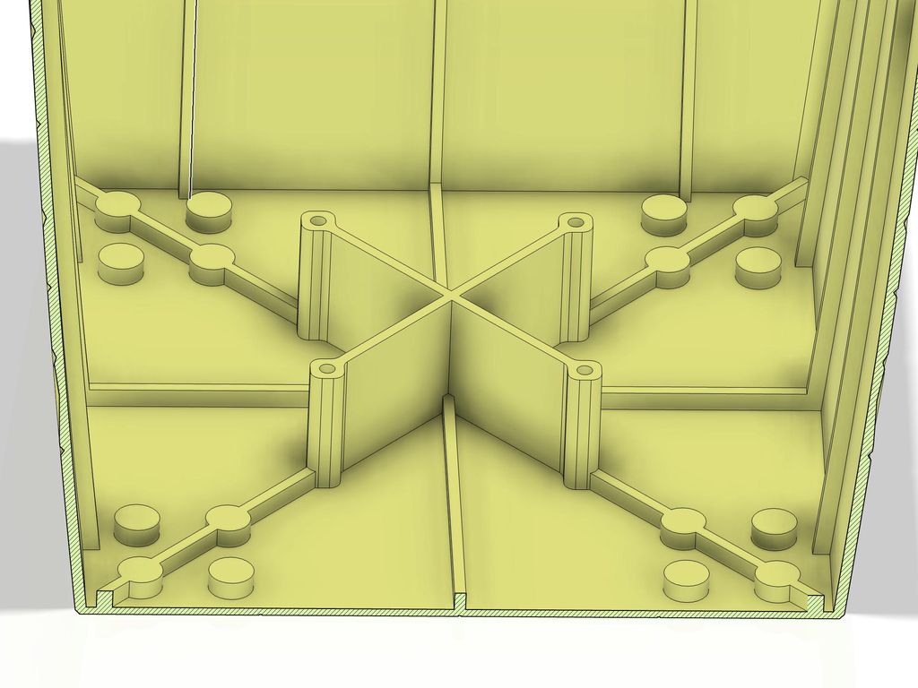
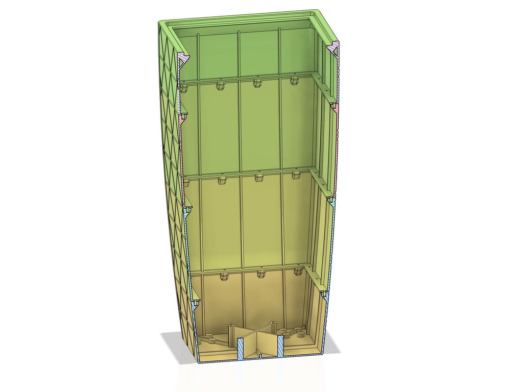
Given that the inner container will weigh approximately 25-30 kg when filled with substrate and water, it wasn’t practical to support this entire weight at the rim of the shell, as many commercial planters do. Instead, I designed the structure so that the weight is supported by the bottom of the shell, allowing for more effective distribution of the load.
To achieve this, I added ribs across the bottom of the shell, along with a spacer element where the base of the inner container will rest. These ribs and the spacer are designed to evenly distribute the weight across the bottom, ensuring stability. Additionally, I included holes for threaded inserts in the spacer. These allow for the attachment of additional elements, such as another spacer, if I decide to use the shell for a shallower inner container in the future.
Attachment Points to Join the Shell Elements
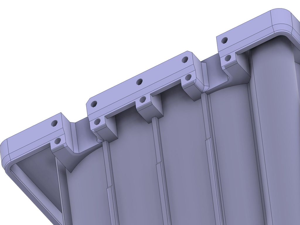
Next, I focused on the top of the lower half of the shell, where I added several features to create a robust attachment system for joining the two halves of the planter.
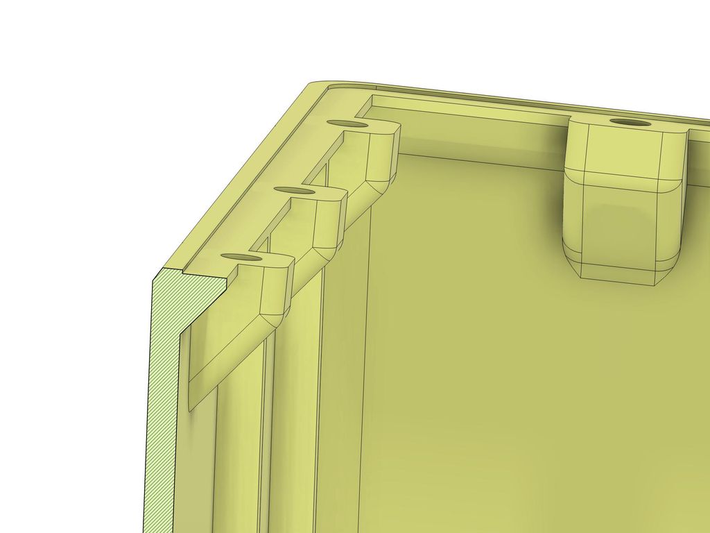
The first feature is a small 6 mm wide rim running along all four sides of the shell. This rim serves a similar purpose as the vertical ribs, enhancing the stiffness of the sides and creating a more stable structure. To support this element during printing, I added a ramp with a 40º overhang, ensuring smooth printing even with challenging filaments.
I then added four small platforms on each side, each with holes for threaded inserts that will secure the shell elements together. These platforms are designed to be compact yet strong, providing enough material around the inserts to evenly distribute the forces across the sides.
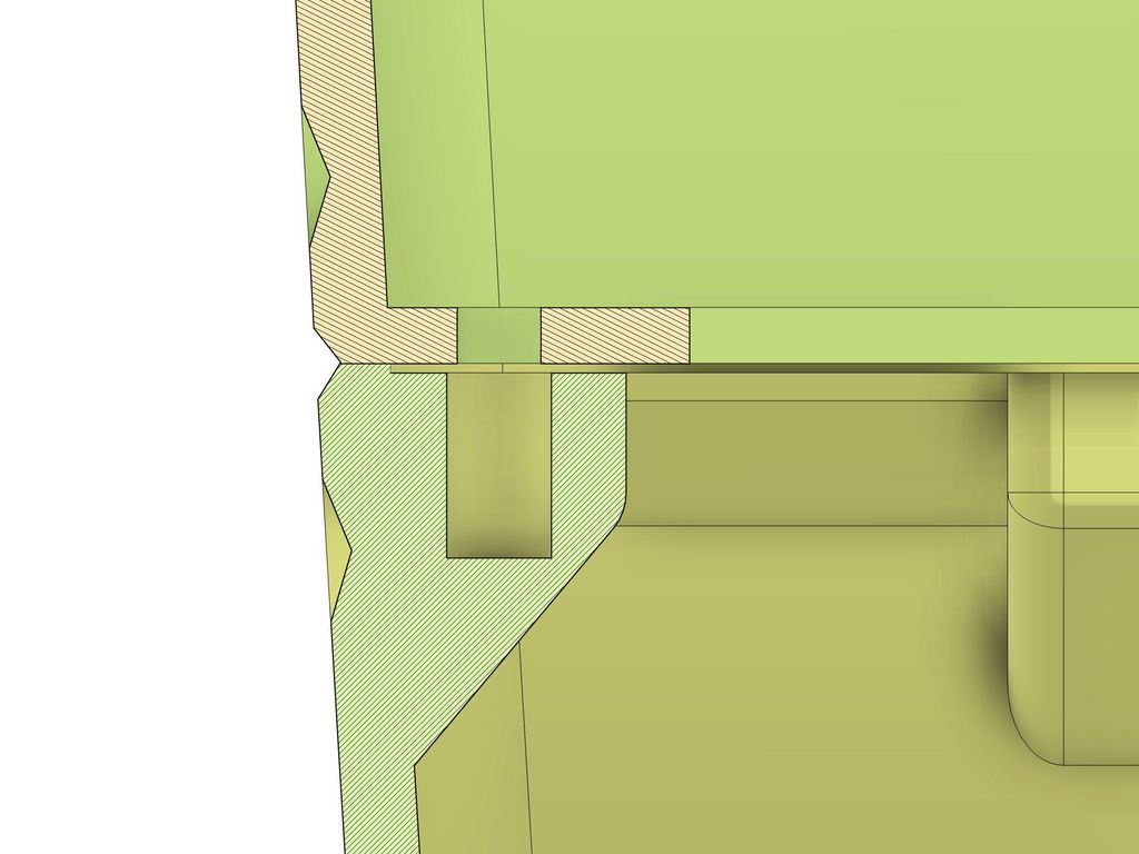
One of the most important features is a small 0.5 mm deep step from the outer rim of the shell to the platform for the inserts. This step is crucial because it ensures that when the screws are tightened during assembly, the bottom of the upper part is firmly pressed against the rim of the lower part.
While 3D printed parts may appear flat, slight deformations can occur due to warping during the cooling process or minor imperfections in the printer bed. These issues often become apparent when trying to join two parts, with the flat upper side of one part not perfectly aligning with the less-than-flat lower side of the other.
The small step I added provides enough space to compensate for these minor inaccuracies, allowing the shell to join seamlessly and giving the appearance of a continuous, flawless part. Additionally, the slight spring force created when the upper part’s rim bends slightly as the screw is tightened helps prevent the connection from loosening over time.
It’s important to note that this step must be minimal. A larger step could cause the parts to bend too much, creating a visible gap on the outside. After several tests, I found that a step height of 0.5 mm worked best, typically resulting in a 0.4 mm step with a 0.2 mm or 0.4 mm layer height, or 0.64 mm with a 0.32 mm layer height. This is why I chose 0.5 mm instead of 0.4 mm, to ensure optimal results.
A Flange and the Top Rim
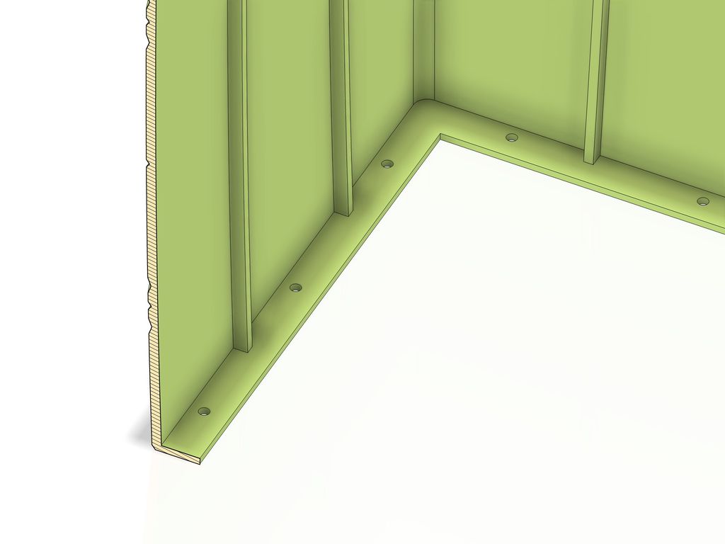
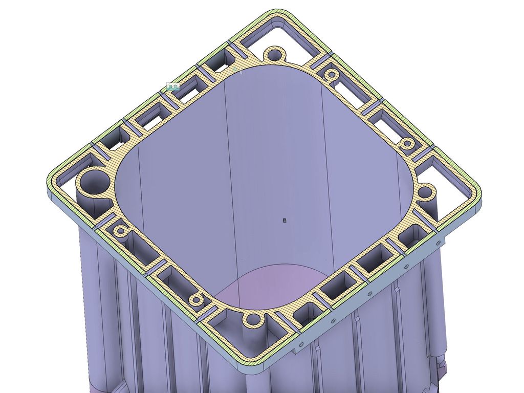
Next, I focused on the upper half of the shell, beginning with the addition of a 16 mm wide flange at the bottom. This flange includes the necessary holes for screws and serves a dual purpose. Beyond its role in securing the two halves together, the flange also ensures that there is sufficient surface area to adhere firmly to the printer bed during printing.
I took a conservative approach here, adding enough material to create a strong adhesion that prevents the part from lifting at the corners. To further reduce the risk of warping, I also included small discs at the corners of the part, which you can see in the print files.
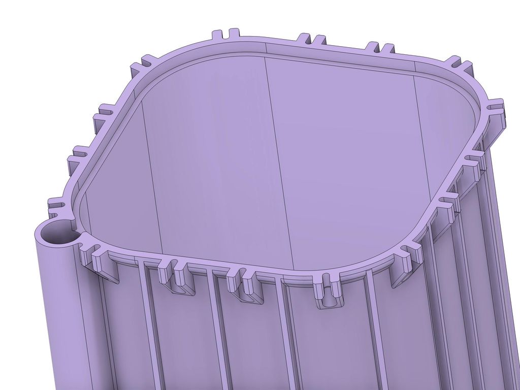
At the very top of the upper half, I designed the rim of the shell. Creating a visually appealing rim for a rectangular planter poses an interesting challenge. With the outer corners already featuring a 10 mm radius and a rim width of about 15 mm, it might seem logical to create a sharp 90º angle on the inside to match the outer radius.
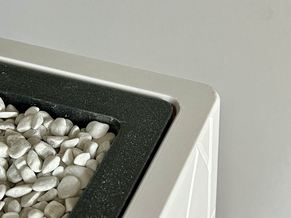
However, the final design needed to consider more than just the outer shell. The planter’s shell will be white, blending with a light gray background, while the inner container will be a dark, almost black, gray. This contrast means that the most visually dominant radius won’t be that of the outer shell, but rather the inner container.
To address this, I designed an 8 mm inner radius that aligns with the 6 mm radius of the container’s rim. Admittedly, this can look a bit awkward during the design phase, but it’s crucial to have a clear vision of the final result and the confidence to maintain these radii, knowing they will contribute to the overall aesthetic.
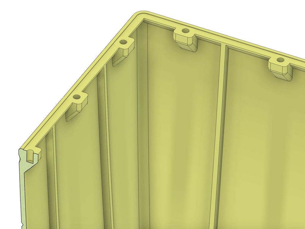
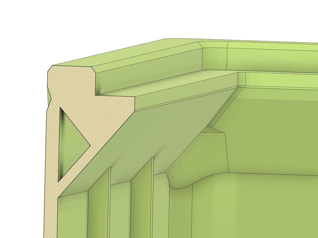
The rim also includes a secondary “step,” where the rim of the inner container will rest. If a shallower container is used, its entire weight will be supported by this step. To ensure it can handle the load, I designed a solid ramp with a 40º angle leading up to the step, incorporating enough material to withstand the forces.
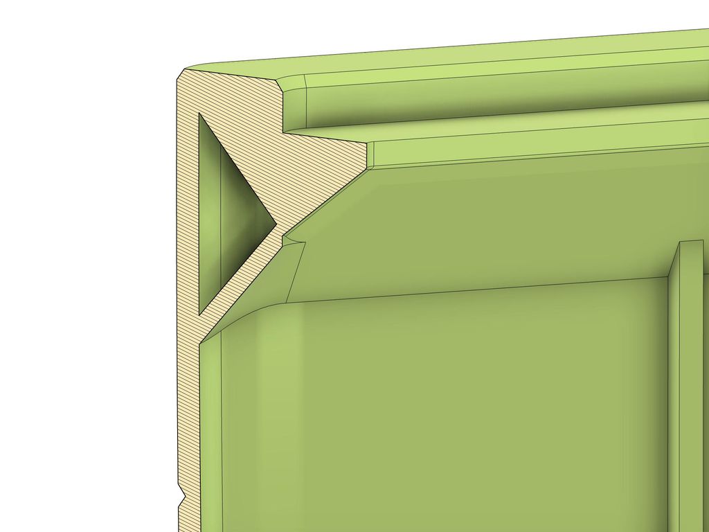
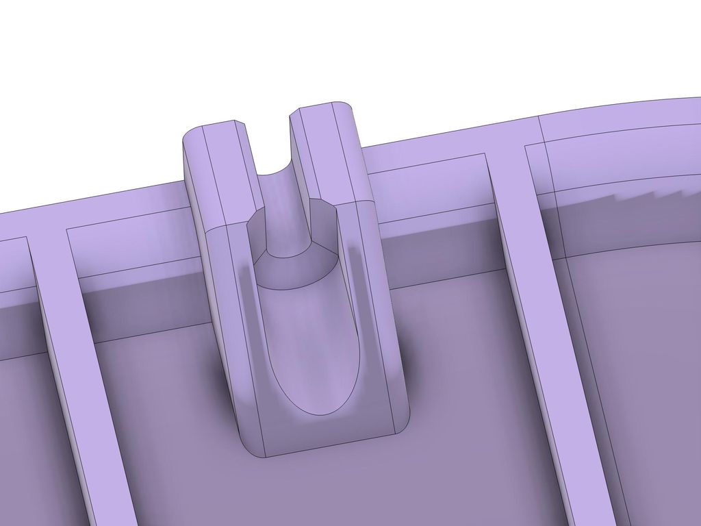
To reduce material usage without compromising strength, I added a triangle-shaped hole in the rim where no significant forces will act. The vertical ribs continue through this hole, not for additional stability, but to help prevent warping.
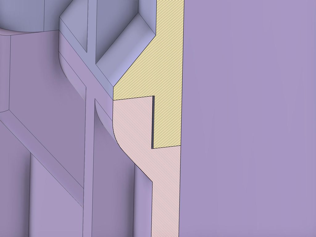
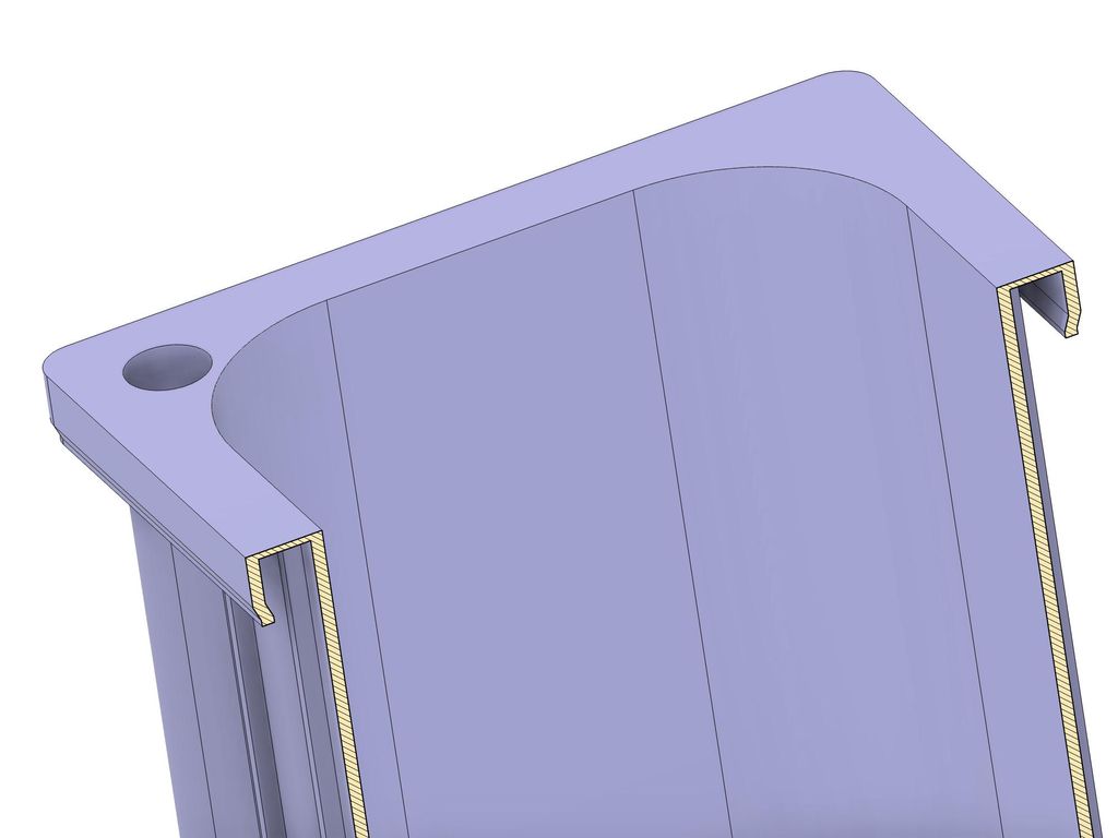
In the image above, you may notice an unusual ramp that extends deeper than the rest of the overhang leading to the top rim. The reason for this becomes clear when you look at a cross-section of the corner at a 45º angle, as shown in the following illustration.
The ramp supporting the upper rim runs around the corner, maintaining the same 40º angle to ensure a smooth print. Since the two radii don’t match, the ramp extends further down to keep the angle consistent. In the upper half, where a minimal 2 mm radius connects the two sides, the overhang angle is steeper than 45º. However, this short distance typically doesn’t significantly impact print quality.
A First Verification with the Slicer
At this stage, I loaded the two shell parts into the slicer to verify their printability. This was an iterative process that involved fine-tuning the dimensions and adjusting radii in areas where I anticipated potential printing issues. One major realization during this phase was the significantly long print time for each part. While I had expected multi-day prints, seeing the actual numbers in the slicer made me reconsider some aspects of the design.
At the time of these prints, I was dealing with hardware issues on my Prusa XL, which have thankfully since been resolved. However, these issues occasionally caused repeated or skipped G-code commands during printing. Although these problems only occurred when using Prusa Connect, I couldn’t help but think about the consequences of a five-day print failing in the last 10% of the job.
I also considered what would happen if, after a few months, I discovered that certain elements—like the attachment points at the bottom or the top rim—didn’t function as intended. Reprinting an entire large part would be time-consuming. It became clear that breaking the design into smaller, more manageable elements would be smarter, allowing for easier replacement and reducing reprint time.
From Two to Four Parts
Initially, I considered adding additional horizontal ribs to further enhance the shell’s stability. However, after deciding to split the shell further, the new split points effectively served this purpose as well. By creating two additional splits, I was able to divide the shell into four parts, each with roughly equal print times.
At each new split point, I incorporated the same attachment system I had originally designed for the middle split. This was a straightforward process, as I could simply replicate the elements I had already created.
Polishing the Shell and Starting the Print
With the shell now divided into four parts, I went through another round of iterative refinement, analyzing the parts in the slicer to identify potential issues and optimize material usage. This process led to 21 revisions of the shell design, many involving minimal adjustments to improve print quality and efficiency.
Once I was satisfied with the results, I began the first print. It might seem unusual to start printing before even designing the inner container, but I intentionally took this approach. I wanted to have physical parts in hand while I continued designing the rest of the planter. This way, I could see if my design assumptions held up and make adjustments as needed if any unforeseen problems arose.
Designing the Inner Container
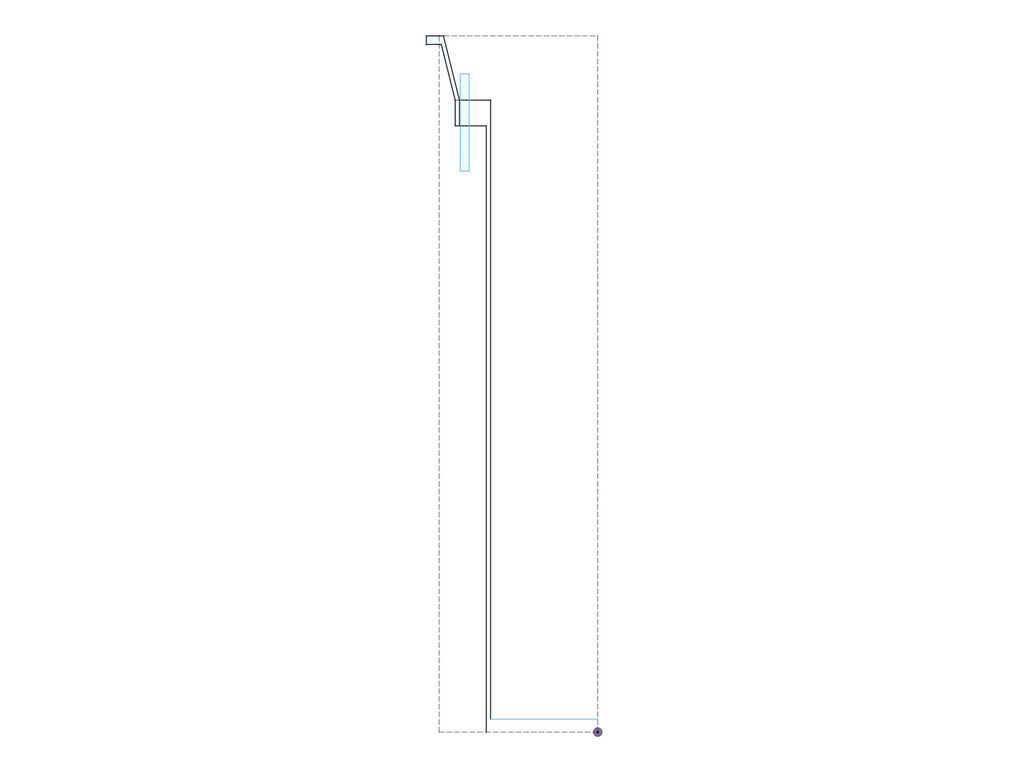
To begin designing the inner container, I started with a rough sketch that outlined the side profile, including the final height, how the container would connect to the shell, and the placement of the handles. These rough drafts are similar to sketches you might scribble in a notebook, but with the added benefit of being integrated into the design, ensuring they aren’t lost.
This sketch doesn’t serve any technical purpose, nor does it directly influence the design features. However, it remains in the Fusion 360 design as a visual reference. The purpose of sketches like this is to maintain a clear overview of the project, acting as a kind of map to remind myself of the overall structure and where I’m currently focused.
Starting with an Extruded Profile
While the design decisions for the outer shell were driven by aesthetics, the inner container prioritized practicality.
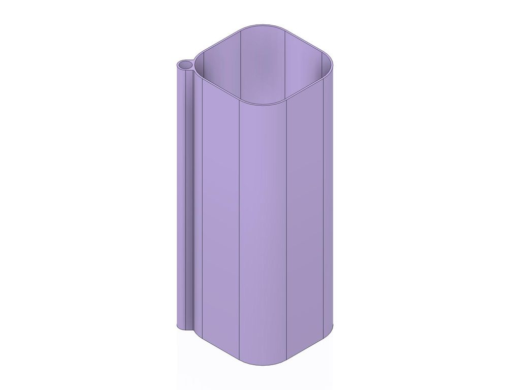
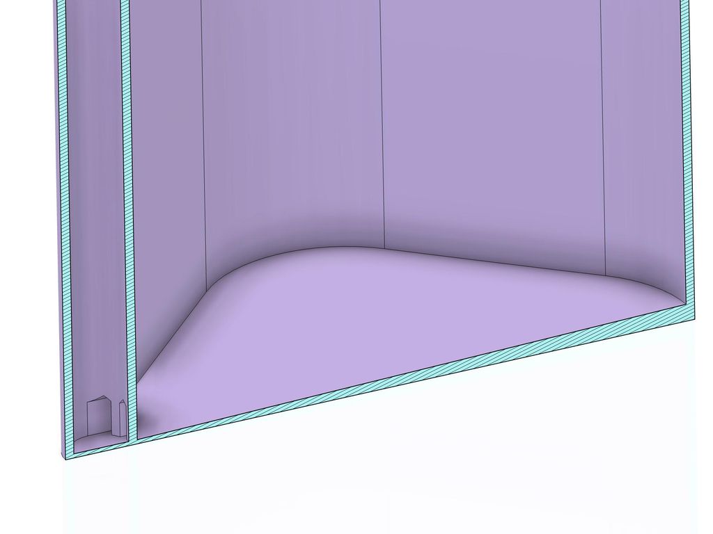
I began with a simple extruded profile that defined the main shape of the container, including an attached water access pipe. Since the container’s design focused more on depth than width, I opted for an inner width of 220 mm, with large 60 mm radii at the corners. This allowed the water access pipe to fit snugly into the corner without protruding too much.
The diameter of the water access pipe was set at 26 mm, based on the size of a water level indicator I found that was suitable for a container of this height. I didn’t spend much time considering this diameter, as it would be easy to print an adapter for smaller water level indicators. Additionally, it would be simple to create a custom solution using foamed polystyrene and a stick, or even insert a fancy electronic sensor to detect excess water.
Adding a Slope and Connecting the Water Access
Next, I added a slope to the bottom of the container to ensure that excess water naturally flows toward the water access point, making it easy to pump out when necessary. I also included four narrow openings to connect the two volumes. These openings needed to be small enough to prevent drainage materials from entering the space, yet large enough to avoid clogging.
To further enhance the stability of the container, I added a series of vertical ribs around the structure. These ribs not only increase the container’s rigidity but also improve the overall stiffness of the part by providing additional support at the bottom.
Doing Some Math
The container will be subjected to significant forces from the weight of the substrate pressing against its walls. Additionally, when the container is lifted out of the shell, it could potentially experience up to 40 kg of force (approximately 400 Newtons), which could stress the layers of the container. To better understand these forces and ensure the design can handle them, it’s useful to do some basic calculations.
Increasing the surface area where the filament bonds is always beneficial, as it improves layer adhesion. With the added ribs, the adhesion area at the perimeter for a 0.4 mm nozzle print is approximately 1500 mm², or 0.0015 m². This results in a stress of 266,666 Pa (or 0.26 MPa), which is well within the estimated tensile strength of PETG in the Z direction, calculated at around 20 MPa.
Splitting the Container and Considering Print Orientation
Just like the shell, the container is too tall to be printed in a single piece, so splitting it into two parts was always part of the plan. Splitting the container also allows for more efficient printing, as the lower part can be printed with the bottom on the printer bed, and the upper part with the rim on the printer bed.
However, this presented a challenge: neither part could easily accommodate a flat platform for the screw heads without requiring an excessive amount of supports. I needed to find a solution to this problem.
In a first step, I added a rim that matched the width of the vertical ribs and ran around the entire container. This rim included a step that overlapped with the wall of the upper part. This design not only increased the surface area where the two parts are pressed together but also prevented water from leaking out the sides when the plant is watered and water flows down the container’s walls.
By making the gap between the rim of the lower part and the wall of the upper part slightly larger at 0.25 mm, I ensured that capillary action wouldn’t draw water up the full 8 mm height.
Returning to the issue of the screw heads, I solved this by using countersunk screws. This allowed me to design an element that could be printed without supports while still being strong enough to securely attach the two container halves.
The countersunk screw head is supported on one half, which helps evenly distribute the pressure forces created by the screw. This prevents any unwanted directional forces and, in the worst case, slightly presses the rim against the wall of the upper part, which is acceptable and even beneficial for stability.
Designing the Inner Platform
One idea I had for the planter was to include an inner platform that would house the handles, the water access hole, the holes for the plant stakes, and the attachment points. This platform would be recessed into the planter, allowing it to be completely covered by decorative gravel. This design hides all the technical elements from view while keeping them easily accessible—simply by brushing away the gravel when needed.
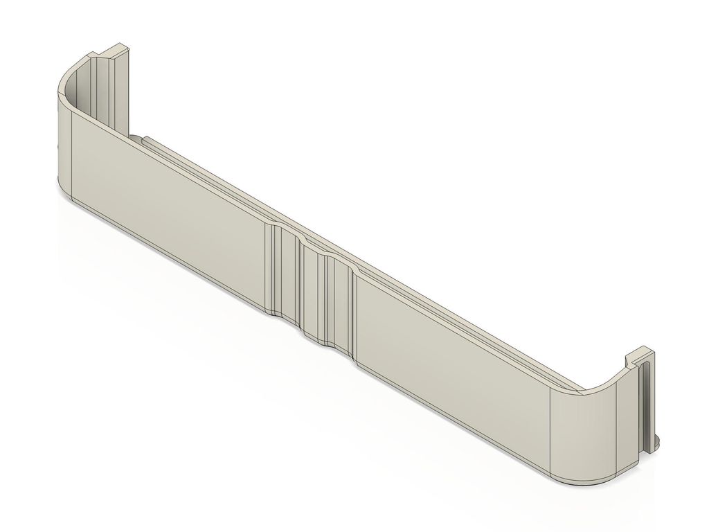
I started by defining the outer profile of the platform, ensuring it seamlessly connects to the short decorative collar that bridges the platform to the rim of the shell. Next, I created a U-shaped profile that forms a lightweight but sturdy frame for the platform. The outer wall of this profile features a small recess at the end, which helps align the collar and locks it into the correct position.
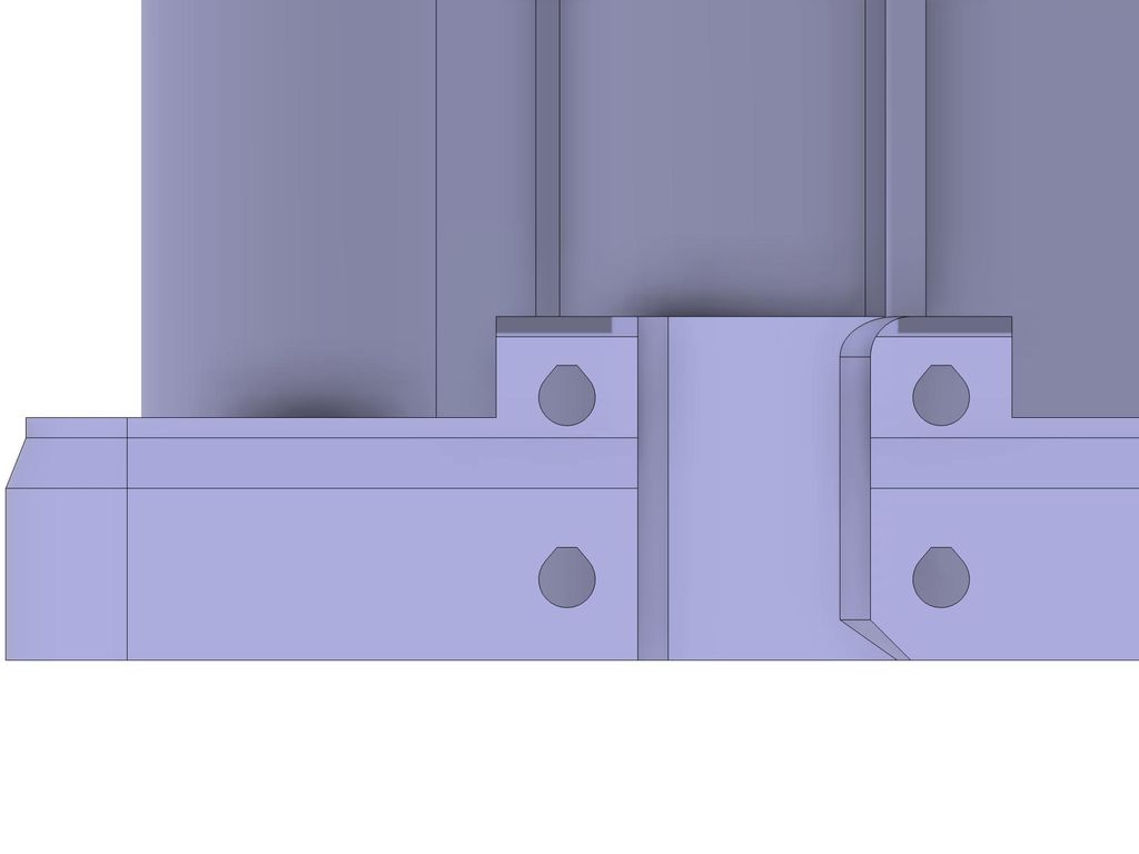
The next step was designing the handle area, which includes cutouts for the handles and ribs that connect the outer wall with the inner walls. I placed the holes for the threaded inserts within these ribs, which will secure the collar to the container.
As shown in the illustration above, the holes aren’t completely round. This design ensures that the overhang inside the hole doesn’t exceed 45º, allowing the printer to easily bridge the small flat area at the top. While this might seem like a minor detail, it’s crucial to prevent the hole’s diameter from shrinking due to material sagging, which can happen with a steeper overhang.
Why So Many Screws?
The design includes ten screw holes on each side to attach the collar wall to the platform, and three sets of 16 screws to connect the four parts of the shell. At first glance, this might seem excessive, but when working with softer materials like PETG, distributing the forces across many attachment points is crucial.
Consider the scenario where the container, filled with up to 40 kg of water and substrate, is lifted out of the shell using the handles. This action would exert significant outward pressure on the handles, pushing them against the collar walls. While threaded inserts provide strong anchor points, they are still only as strong as the surrounding perimeter material and the light infill around them. It doesn’t take much force to rip them out if they aren’t properly supported.
To prevent catastrophic failures, such as the container breaking apart when lifted, it’s important to distribute the forces evenly across multiple attachment points. This approach balances cost and effort with a sufficient safety margin.
Personally, I prefer to err on the side of caution. The last thing I want is to discover that I underestimated the forces in real-world use. I’d rather add a few extra screws than risk having one too few.
Final Touches
To wrap up the design of the container, I added holes for the plant stakes that would be attached to the container and included additional holes for threaded inserts to allow for the future attachment of other elements. I then designed the collar to align seamlessly with the rim of the shell, creating a smooth transition to the recessed platform.
I also needed to design smaller components, such as the handles themselves, along with caps to close the water access hole and the plant stake holes when they’re not in use. The inserts for potential extensions were designed to be easily sealed with two screws.
To ensure the planter’s stability, I created feet for the shell, incorporating ribs to provide extra support to the bottom of the planter in case my weight calculations proved to be off.
With these final touches, the design was complete. At this point, the shell of the planter had already been fully printed, and I was pleased to find no issues with the design. Satisfied with the results, I moved on to printing the container and all the remaining parts.
Printing the Parts
For this planter, I planned to print at least the shell using a 0.4 mm nozzle with a 0.2 mm layer height. This choice was driven not only by the superior aesthetic results but also by the desire to leverage the sandwich material properties naturally created by 3D prints with light infill. The combination of two solid perimeter layers with a flexible gyroid infill significantly increases the stiffness of the walls.
I based this decision on my experience from numerous prints and experiments with different layer heights, nozzle sizes, and settings. However, I’d like to delve into the various factors that influenced this choice.
Finding the Right Compromise
One of my primary goals was to produce a planter that looks flawless without any post-processing.
During my research, I experimented extensively with larger nozzle sizes, such as 0.6 mm and 0.8 mm, in an attempt to achieve high-quality prints. However, at least at the time of writing, the results with larger nozzles didn’t meet the high standards I set for decorative prints. One of the main issues was the visibility of seams, which, while acceptable for practical prints, were too noticeable for a surface that needed to be perfect.
In contrast, using a 0.4 mm nozzle consistently produced nearly flawless prints, even with the challenging white filaments. I believe that it’s only a matter of time before improvements in firmware, PrusaSlicer updates, and optimized profiles enable the Prusa XL to produce beautiful prints with larger nozzles.
But nozzle size affects more than just the appearance of the print. Larger nozzles can print thicker layers, allowing more material to be deposited in a shorter amount of time, which significantly reduces print time.
The table below compares the print times and filament usage for part LR2442-111, using the default structural or quality profile in PrusaSlicer for PETG with different nozzle sizes and layer heights:
Nozzle Size
Layer Height
Duration
Filament Usage
0.4 mm
0.20 mm
37 hours
761 g
0.6 mm
0.32 mm
25 hours
1068 g
0.8 mm
0.40 mm
20 hours
1235 g
As the table shows, a print with a 0.8 mm nozzle is nearly twice as fast as the same print with a 0.4 mm nozzle. However, this comes at the cost of approximately 60% more material usage when using the same settings with two perimeters.
Choosing the Right Settings
I used the 0.2 mm structural profile in PrusaSlicer as the starting point for all my prints. However, I prefer to make a few adjustments to better suit my needs. One notable change I made was switching the infill pattern from the default grid to the gyroid pattern.
For all my prints, I opted for a 15% gyroid infill. The gyroid pattern is advantageous because it doesn’t introduce additional tension into the printed parts, unlike the grid pattern. As the filament cools and contracts, the curved lines of the gyroid infill simply stretch slightly, without exerting pressure on the surrounding perimeter lines.
Another important setting I activated was “Avoid Crossing Perimeters.” This option plans travel moves to occur only within the perimeters, which significantly reduces stringing. On a fast printer like the Prusa XL, enabling this setting usually only adds a few minutes to the total print time.
The image below compares two prints: the left one without the setting activated and the right one with it enabled. The blue lines indicate the travel moves.
While this setting doesn’t completely eliminate stringing—since filament can still be dragged around corners—it does improve results by ensuring that travel moves start into the infill rather than immediately crossing the perimeter.
There’s still room for improvement, though. It would be beneficial if the travel movements could describe a soft curve around corners instead of making sharp turns. This change could speed up prints with this setting enabled.
Side Effects of Spool Join
Given the significant amount of filament required for these prints, and since Fiberlogy spools contain only 850g of filament, I used the spool join feature of the Prusa XL to automatically switch to a new spool when the first one ran out. However, I didn’t anticipate the slight, almost imperceptible offset between the nozzles of the two tools.
Unfortunately, this minimal offset became quite noticeable on the otherwise smooth and even surfaces the printer produced. I had never observed this shift before on more practical prints.
After experiencing this issue with spool join, I reverted to manual filament changes using the same tool. This approach required a bit more planning, as I had to time the prints so that filament changes occurred during the day rather than in the middle of the night. This strategy worked for all but one print, where I opted to change the filament early to allow the print to run through the night without interruption.
Final Thoughts on the Printing Process
I’m pleased with the overall outcome, despite the minor challenges encountered. The settings adjustments, the decision to manually change filaments, and the choice of a 0.4 mm nozzle all contributed to achieving a high-quality print with minimal issues.
These experiences have further refined my approach to large-scale 3D printing, and I’m confident that future projects will benefit from the lessons learned here.
Assembly
Before assembling the entire planter, I applied two coats of Epodex Water-Based Polyurethane to the lower part of the container. While PETG is generally water-tight, I was concerned that the additional weight of the substrate and drainage layers, or the plant roots themselves, might penetrate the small grooves of the printed layers, potentially causing cracks.
Polyurethane bonds exceptionally well with PETG, creating a durable, impenetrable, water-tight layer. Working with polyurethane sealing paint, like the one I used, requires some experience, but I’m confident that containers sealed with this material will remain water-tight for a very long time.
After applying the sealant, I installed all the threaded inserts into the prepared holes. I used M4 inserts from CNC Kitchen, which, in my opinion, are of the highest quality among those I’ve tried.
To insert the threads, I used a Weller soldering iron with precise temperature control. By setting the iron to the PETG printing temperature (240ºC), the inserts smoothly glided into the prepared holes with almost no pressure required.
Aside from these steps, the assembly process was straightforward. I began with the shell, working from the bottom up. I used 16 mm M4 screws with small 4.5 × 1.4 × 12 mm spacers to join the parts. First, I loosely inserted all the screws without tightening them, then started securing the parts at one corner.
I aligned the two parts at the first corner before tightening the screw, then moved to the opposite corner. After securing the remaining two corners, I worked clockwise around the shell, carefully aligning the parts before tightening each screw.
For the inner container, it’s best to first join the two large halves and then place them inside the collar. Next, attach the two handles to the container and slide the collar up until it locks into place, allowing you to secure it with screws.
Final Thoughts and Reflections
Reflecting on this project, the journey of designing and 3D printing this giant planter has been both challenging and rewarding. It pushed the limits of what I thought was possible with large-scale 3D printing, requiring me to delve deep into the nuances of design, material selection, and printing techniques.
One of the key takeaways from this experience is the importance of planning and iteration. Breaking down the project into manageable parts and iteratively refining the design not only made the process more feasible but also allowed for the creation of a highly functional and aesthetically pleasing final product. The detailed research and extensive testing of materials, especially the choice of white PETG, were crucial in achieving the desired balance between durability and visual appeal.
Another valuable lesson was the realization that even the smallest design decisions can have a significant impact on the final outcome. From choosing the right infill pattern to the placement of tension release grooves, each choice contributed to the overall success of the project. The challenges I faced, such as dealing with warping and adjusting to the quirks of the Prusa XL, ultimately led to a more robust understanding of the capabilities and limitations of large-scale 3D printing.
Overall, this project has not only expanded my skills and knowledge but also reinforced the idea that with the right approach, it’s possible to bring even the most ambitious designs to life.
Conclusion
The creation of this giant 3D-printed planter has been an enriching journey from concept to completion. By carefully considering every aspect of the design process—from the initial sketches to the final assembly—I was able to produce a planter that is both functional and visually striking. This project is a testament to the potential of 3D printing, demonstrating that with thoughtful planning, innovative design, and meticulous execution, even the most challenging ideas can become a reality.
I tried parametric design and published a set of heart-decorated 3D-print boxes in 500 sizes (35–120 mm). I explain part numbering, two lid fits, and printing tips, and I've shared the STLs on GitHub. Read the full post to find the exact size and download files for your printer.
I walk through creating custom wiring for the snowflake decoration, covering layouts, cable choices, current and voltage-drop math, and a simple power supply board for Pimoroni kits. If you want practical tips and diagrams to wire your own design, please read the full guide.
I take you through part two of my cheap plant-watering sensor project, testing a prototype: power draw, LED impact, oscillator and MCU startup timing, voltage-divider checks, firmware inputs, and PCB preparation. If you want to see the detailed measurements and next steps, I invite you to read the full post.
I walk you through how I get camera-ready solder work: choosing the right iron and pliers, selecting solder and flux, careful prep, cutting and reheating for shiny domes, plus cleaning for macro photos. If you want neater prototypes or better product shots, read the full step-by-step guide.
I tested a simple technique to strengthen FFF prints by adding a zig-zag vertical link between the outer and inner perimeter. My demo gcode and findings show how peaks fuse layers and slow crack propagation. If you print regularly, read the full post to see my method and limitations.
I swapped my LM386 for an NXP TDA7052 to reduce distortion and gain more volume. The TDA7052 needs only power, an input and connects to an 8Ω speaker; I added a volume trimmer (I used 47k, 10k also works). Read the full post for the schematic and wiring details.