published: October 29, 2021 —
last modified: October 23, 2025
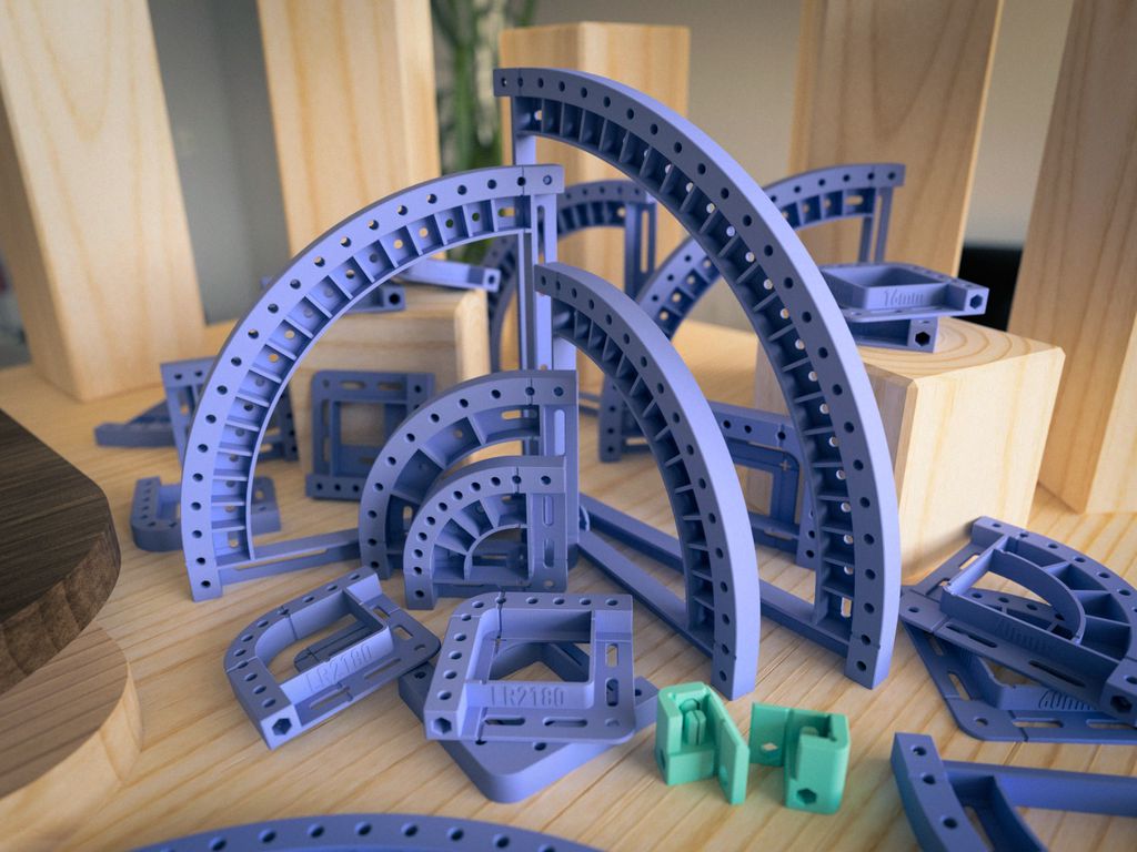
Sometimes I like to have rounded corners in my woodworking projects. It seems many people like to soften the spiky ends of their panels because there is a huge range of templates for routing. If you own a 3d printer, it is handy you can print just the template with the size you actually need.
I thought it will not hurt to add a few more 3d-printable corner templates, specially designed for 3d-printing.
Table of Contents
My Design Goals
I designed the corner templates from the ground up with 3d-printing in mind. All dimensions and features are chosen in a way, to make the best use of the unique features of 3d-printed objects. Also, the new objects had to be versatile and not just work for one fastening/routing method.
Perfectly 3d-printable for 0.4mm nozzles, 0.2mm layer height without supports.
Multiple ways to align and fasten the template to the workpiece.
Robust design, minimizing bending when softer materials are used (e.g. PETG).
Elements of the Templates
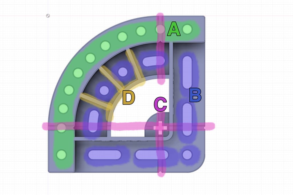
Directly along the edge, there is a row of ⌀4mm holes (A) to fasten the template to the workpiece using screws. I personally prefer to screw the template to the backside of the workpiece for routing. The template uses only ⌀4mm holes and slots, which perfectly work with ⌀3mm and ⌀3.5mm woodscrews. I recommend using screws with a button or pan head, but it is also possible to use countersunk screws. If you use countersunk screws, either fasten them very carefully or add a washer, PLA and PETG easily deform and crack if you fasten the screws with too much force.
In the flat support area, are more ⌀4mm holes and slots (B) to fasten the template. You can use them to fasten the template to the workpiece if you plan to use the router on top of the template. With the slots, you can easily align the template precisely before you fasten the screws.
All templates with a radius of >=20mm have the centre and the end of the corner marked with a cross and embossed lines (C). These elements let you quickly verify that the template has the correct size and is properly aligned. There are always two holes centred on this line (where “C” and “A” cross each other).
The templates with a radius >=50mm have an inner ring with ribs behind the actual edge with the radius (D). This ring is the best place to fasten the template if you cannot use the screw holes on top (A). It also makes the larger template more rigid, so they don’t deform easily if the router is pressed against the outer curve.
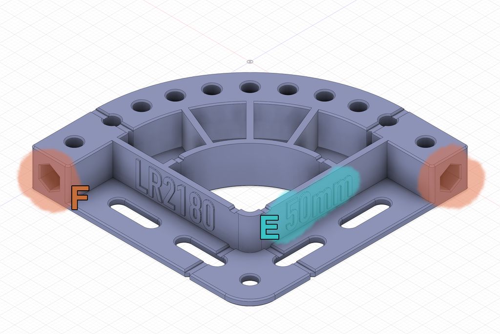
The radius of the template is written on the inner rib (E), so if you print a whole collection of these templates, you easily find the one with the right size.
Also, there is a hexagonal hole with an inner diameter of ⌀6mm on both sides of the template. I added this hole for attachments and extensions. In the simplest case, you can use a 6mm dowel to join two corner templates. Or, you can design attachments like the guides I created.
The Snap-In Guides
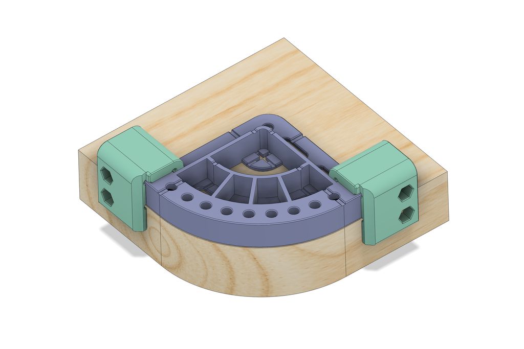
If you like to align the corner template just using your tactile feel, the snap-in guide elements are the perfect solution for you.
These two elements can be attached to any metric corner template (at the moment I write this, there are no guides for the imperial templates yet). The tight tolerances will let you add these guides to the template, where they snap securely into place. If printed correctly, there is almost no play.
Now you simply pull the template lightly towards the centre of the workpiece, until the corner aligns at the corner.
At this point, you can either fasten the template using screws, or if you use a router table, hold the template with one hand in place while you work on the corner (I do not recommend this).
If you use a ⌀20mm trim-cut bit, these guides will stop the router 2mm after the corner on both sides. With smaller diameters, you will get a longer working distance on the straight part of the template. My design will *theoretically *allow trim-cut bits with a diameter of up to ⌀34.4mm, but I recommend a maximum of ⌀30mm.
Filenames and Dimensions
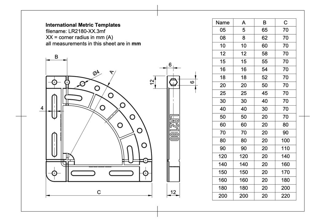
There are international metric templates and a small set of templates with imperial units for people in the US. You find the dimensions of the metric templates in the following diagram:
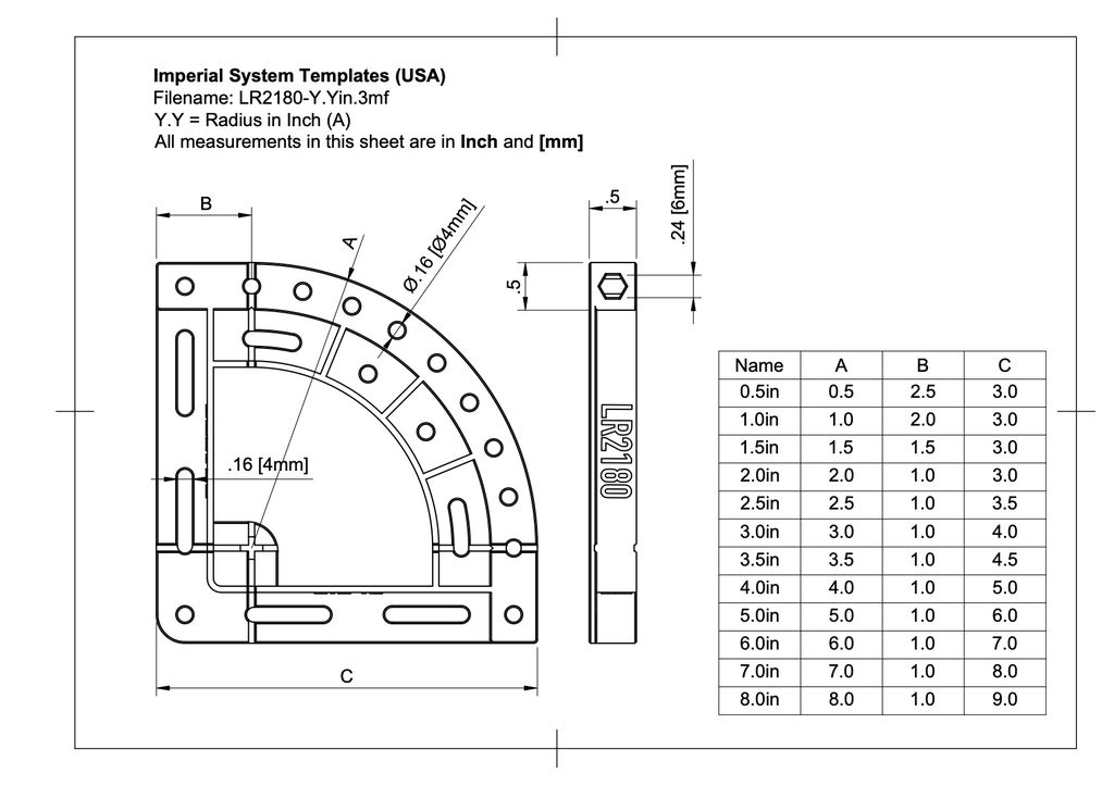
The set with imperial units has slightly adjusted dimensions:
Because of the 0.2mm layer size, the height of the imperial units template isn’t exactly half an inch, but actually 0.496063 inches. This is the result of optimizing the object to 0.2mm layer height for 3d-printing. I hope this discrepancy is irrelevant for woodworking.
How to Print the Templates
If you are using a Prusa Printer, or just the PrusaSlicer, you will find example projects in the files.
Materials: I personally tested the template with PLA and PETG. Both filaments work great, but I prefer PLA because of the rigidity. If you have filament with large diameter changes, this will affect the quality of the printed object.
Nozzle Size: The models are designed for a nozzle size of 0.4mm. (A nozzle size of 0.8mm could work, yet, I would not recommend it.)
Layer height: All objects are optimized for a layer height of 0.2mm. If you slice the objects with this layer height, you will get the best results. Alternatively, a layer height of 0.1mm will work as well but is probably a waste of time. Every other layer height will probably produce irregularities because the features do not perfectly match.
Quality setting: In PrusaSlicer, you should choose the setting with “Quality” and not speed. This is important to get a perfect uniform radius in the template. For one the slower printing speed will produce a better surface and the Gyroid infill prevents irregularities at the round corner.
Perimeters: Especially if you print the templates using PETG, print at least 3 perimeters. It will increase the rigidity of the object, which is important if you roll the trim bit over it. Because of the design and placement, adding more top and bottom layers make no big difference.
Orientation/Supports: The prints do not need supports. They are always oriented with the largest flat surface to the printer bed. Usually, in my designs, I add rounded corners along the vertical axis and chamfers along the horizontal axis.
Scaling: Never scale my models. They are carefully designed to get the best results with a defined layer height and nozzle size.
Seams: With these templates, you may check where the slicer will place the seams on the print. You do not want to get seams at the radius of the template and also not at the flat inner surfaces of the guides.
Download
You can download and preview all files on the Prusa Printers Platform:
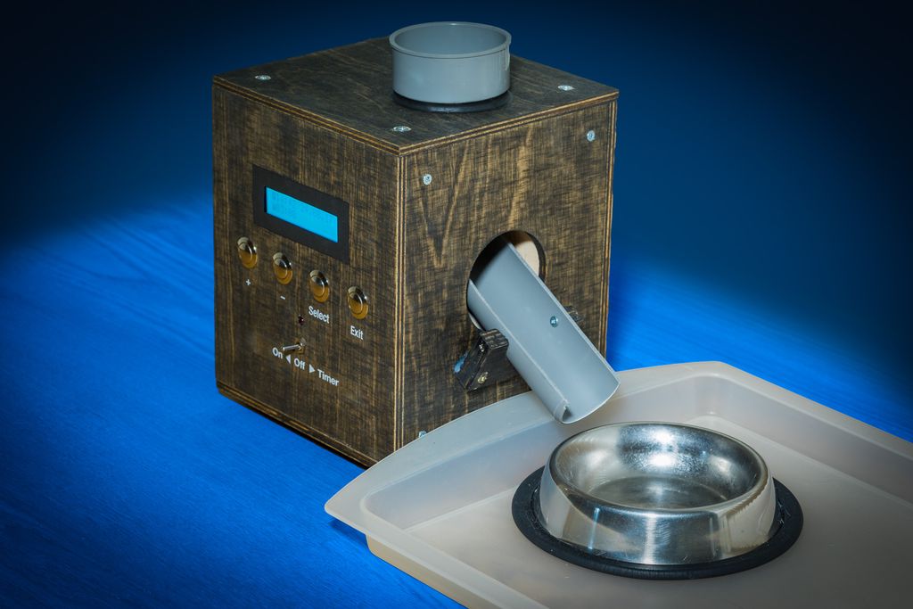
I built a simple, single-portion programmable cat feeder in about four days using rapid prototyping. I describe the Fusion360 sizing, plywood shell, servo mechanism, electronics, and the issues I encountered with breakout boards. If you're curious, read the full post for parts list, wiring and source code.
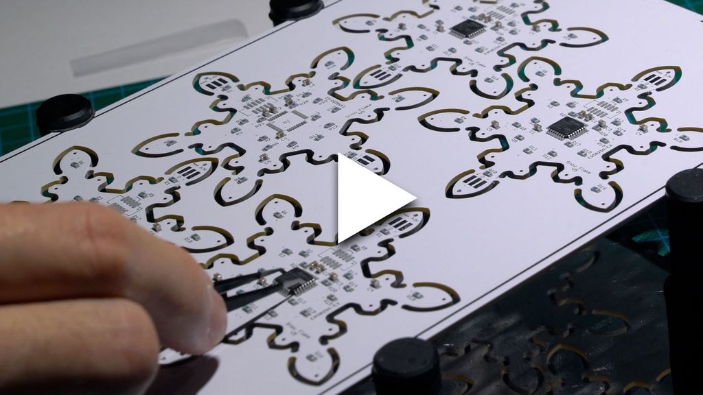
I walk through assembling the component side of my snowflake panel, showing stencil-applied solder paste, placement of 105 resistors, capacitors, headers and chips, and sped-up hot-air soldering. I test the LEDs at the end — please read/watch the full post if you'd like the complete build and tips.
I built a simple USB-to-3.3V power converter for my snowflake decoration using a Traco TSR2-2433 and a laser-cut acrylic case with glow-in-the-dark engravings. I'll walk through the board, Fusion360/Eagle workflow, laser cutting and painting - read on if you want the files and build notes.
I've been developing software for over 20 years and share how my language preferences shifted—from assembler and C to Python, Swift, C++, Go and Rust. I outline use-cases and trade-offs in a personal, practical way; if you're deciding what to learn, please read the full post for detailed guidance.
I've finished testing a new set of tall storage boxes designed for 3D printing. They're stackable with my flat and regular boxes, with reinforced walls and improved corners for cleaner prints. Download the free sample set or read the project page and catalog for full designs.
I walk you through how I get camera-ready solder work: choosing the right iron and pliers, selecting solder and flux, careful prep, cutting and reheating for shiny domes, plus cleaning for macro photos. If you want neater prototypes or better product shots, read the full step-by-step guide.