published: August 21, 2021 —
last modified: October 23, 2025
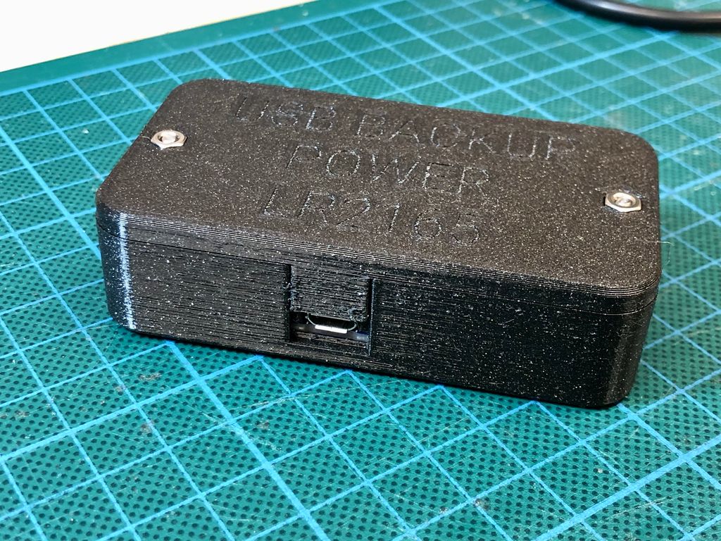
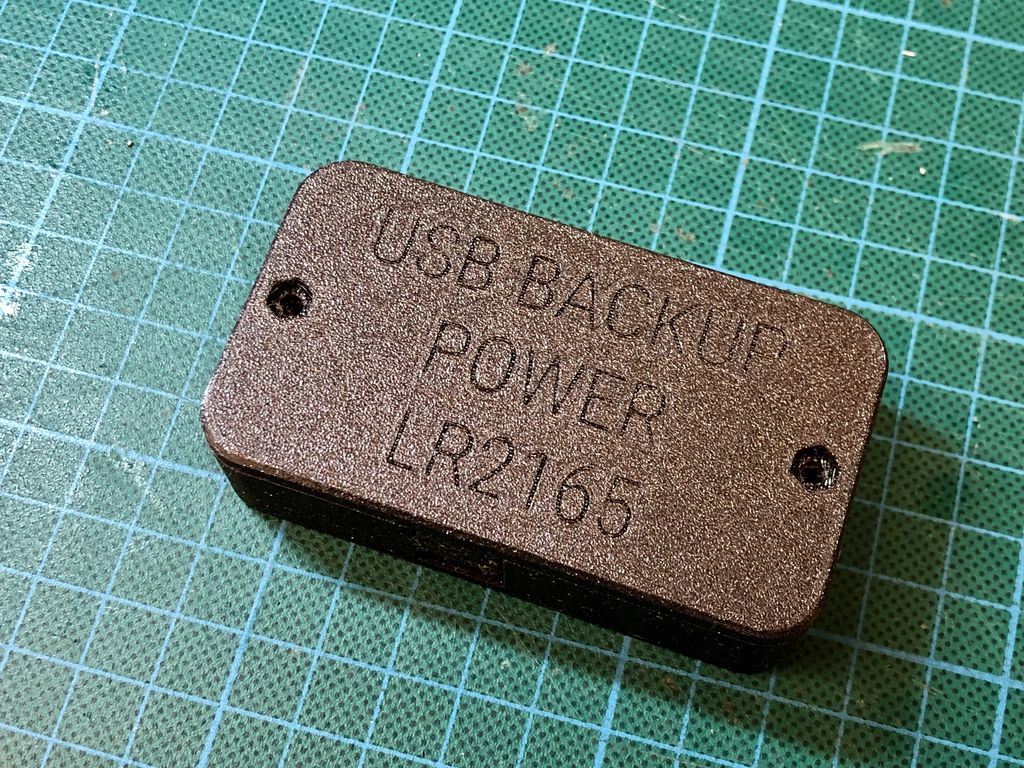
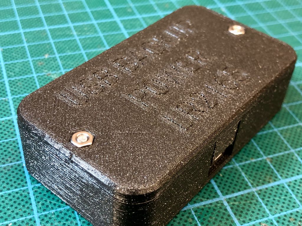
I made a simple 3d printed enclosure for Adafruit’s PowerBoost 1000C and a 1200mAh or smaller LiPo battery. This post contains all the files you need for the print, a list of components, and assembly instructions.
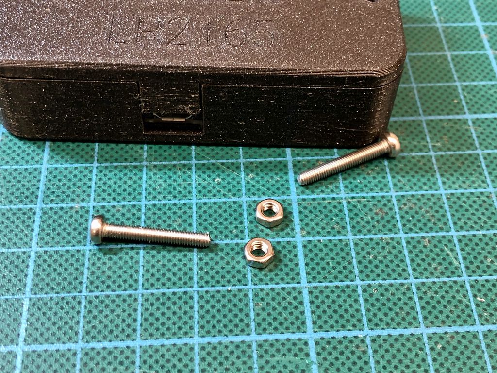
My design uses three simple parts with tight tolerances. They are held together with two M3 screws and two nuts. The parts enclose and protect the board and battery securely, with enough space for heat dissipation. Additionally, there is space for a miniature switch, to turn off the power.
The goal of this project was to convert the board into a small portable device, to protect the electronics and battery from damage. I designed it after I accidentally shorted the circuit with another USB cable that was laying around. 😅
I really like the Adafuit PowerBoost 1000C: It is a versatile breakout board to power projects from lithium-ion batteries. The board comes with a micro USB socket to charge the battery and a USB-A socket to plug any USB-powered project into it. In this configuration, it is perfect to e.g. either power a Raspberry Pi, Feather board from the battery.
Because of the built-in load balancing, it is also great to use as a backup power system. Where you keep running the project from a USB power source, but in case of a power loss, the board automatically switches to the battery.
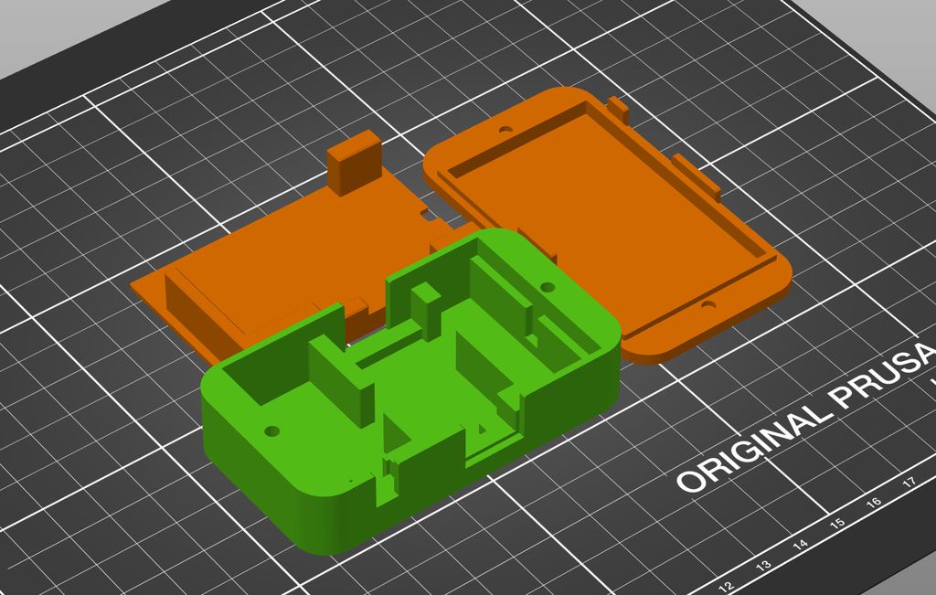
In the ZIP file, you find separate files for all three parts, and one file “LR2165-101_102_103 Print.3mf” prepared for the PrusaSlicer application. It contains all three parts, already correctly arranged.
Print the files in the orientation shown above.
Use PETG as printing material.
Use 0.2mm layer height. The models are optimized for this layer height.
No supports are required.
Prepare the Printed Parts
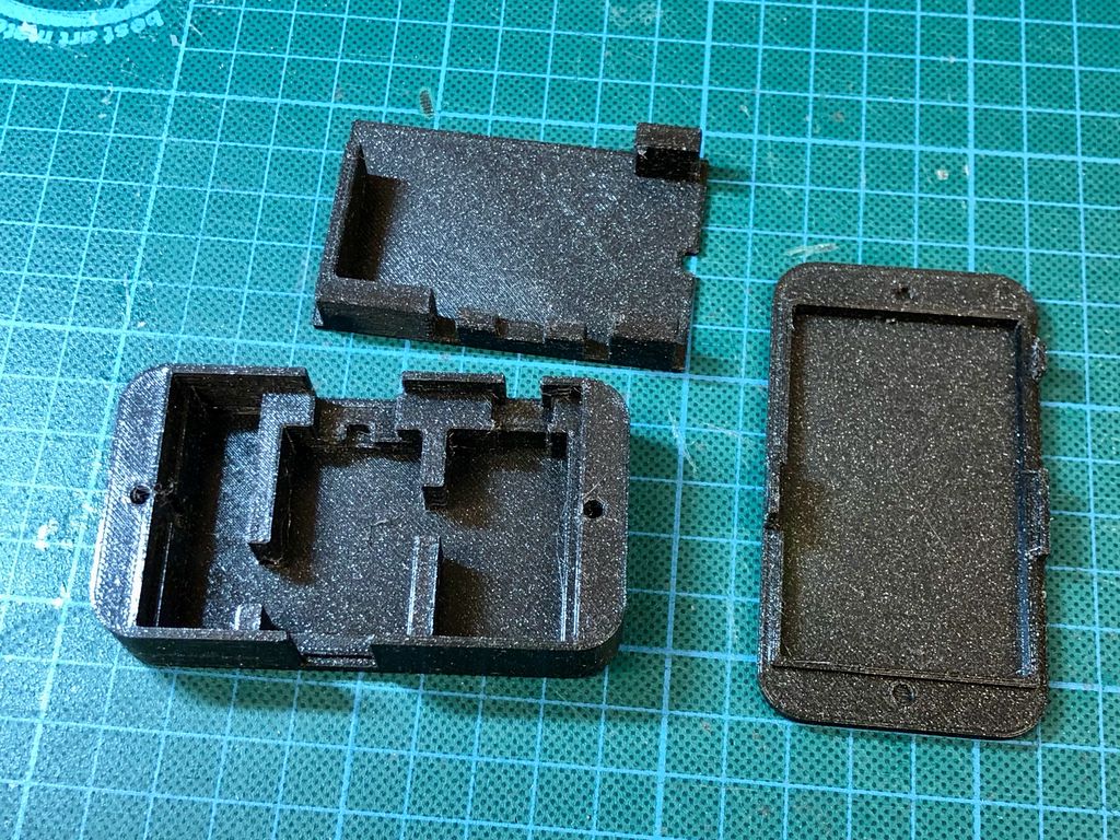
After printing, you need to drill out the two screw holes for part 101 and 103. Use a 3.2mm or 3mm drill and use the existing hole to center the drill in the right position. It will remove the small printed cap from the hole.
Alternatively, you can also use a small knife, yet drilling is much easier and also cleans the hole from any strings.
Prepare the Board and Switch
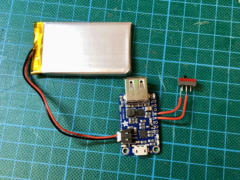
First, solder the USB connector to the board. Make sure it sits flush on the board and not at an angle.
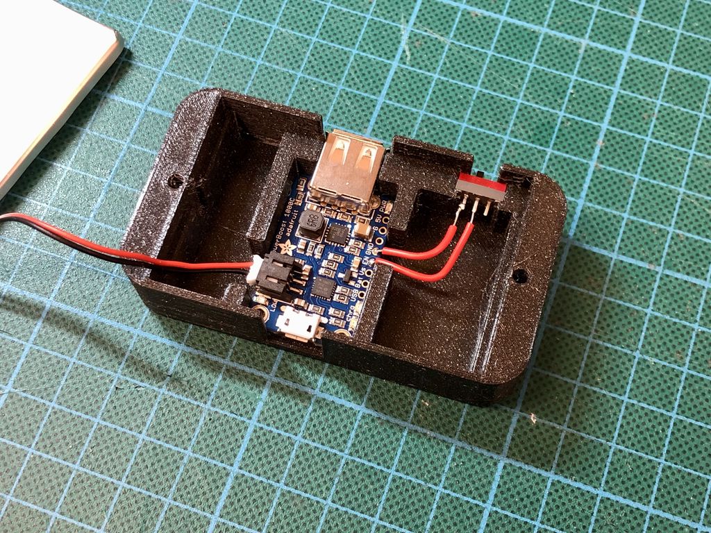
Next, solder the switch to the board, connecting the “EN” and “GND” connectors. Also, attach the battery to the board. It is easier to connect it beforehand.
Insert the Board and Switch into the Lower Shell
Insert the board and switch into the lower shell. Push the board down by pressing down on the two USB connectors. The USB-A connector should be flush with the top edge. On the other side, the board should sit flat on the enclosure.
Push the switch into the enclosure. It should also sit flush in its space.
Now is a good time to test everything the last time:
Is the battery properly connected? (blue or red light is on - change the switch of not)
Does the switch work? (blue light goes on/off)
Is there power on the output? (connect a device)
Does an attached power source on the input charge the battery? (orange/green LED)
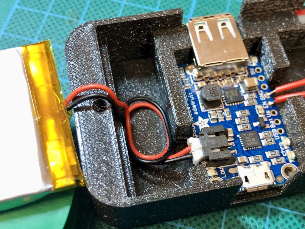
Depending on the length of the battery cable, create a small coil in the center of the small space nearby.
Insert the Battery
Now insert the middle part of the case.
Pull the battery cables through the small hole at one end of the middle piece, so the battery lies flat on it. There should be no strain on the cable.
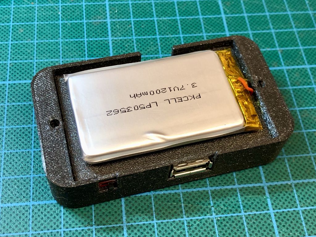
Press the middle piece firmly down, until it is flush in the enclosure. It should hold both the USB connectors and the switch down in its place.
Use one or two small pieces of double-sided tape to hold the battery in the middle of the platform.
Add the Top Shell
Add the top shell to the enclosure.
It should slide easily on top without any force needed. Especially make sure there is no pressure on the battery. There should be a small air gap between the battery and the case.
Add the Screws
First, add the two nuts into the top shell. Next insert the screws from the bottom and gently fasten them. Do not use too much force, it may break or deform the printed parts.
Well done!
Conclusion
I hope you found this simple enclosure useful. It converts the PowerBoost 1000C board into a simple power bank or backup power device, without the risk of dangling cables, shorts or accidentally damaging the battery.
If you have any questions, missed information, or simply want to provide feedback, feel free to comment below. 😄
I often reach for TE's Micro‑MaTch connectors when I need compact, hand‑solderable board-to-board connections. They saved me routing space and allowed SMD pads on tiny sensor boards. I share my requirements, examples, and practical tips — please read on if you're choosing connectors for small projects.
Posted on 2019-07-10— C++, Improve your Code, Learn
I walk you through how real-time counters work, why integer overflow is usually harmless when you treat time as relative, and practical, Arduino-ready comparisons and code examples to avoid timing mistakes. If you want concrete patterns and simple tests, read the full post.
Posted on 2019-07-05— C++, Improve your Code, Learn
I walk through a practical, minimal event-based approach to firmware using Arduino examples. Step by step I refactor blink sketches into modular events, introduce a millisecond timer, prevent skipped events, and encapsulate logic into classes and modules. Read on to follow the examples and apply them to your projects.
I walk you through how I get camera-ready solder work: choosing the right iron and pliers, selecting solder and flux, careful prep, cutting and reheating for shiny domes, plus cleaning for macro photos. If you want neater prototypes or better product shots, read the full step-by-step guide.
I’ve published a simple firmware example for the Always-On project, built for PlatformIO and Visual Studio Code with my HAL adapted for Adafruit Feather M0. It explains the hardware mapping, motion-triggered lighting behavior, and timing options. Please read the full post for setup instructions and the GitHub link.
I take you through part two of my cheap plant-watering sensor project, testing a prototype: power draw, LED impact, oscillator and MCU startup timing, voltage-divider checks, firmware inputs, and PCB preparation. If you want to see the detailed measurements and next steps, I invite you to read the full post.