published: April 5, 2021 —
last modified: October 23, 2025
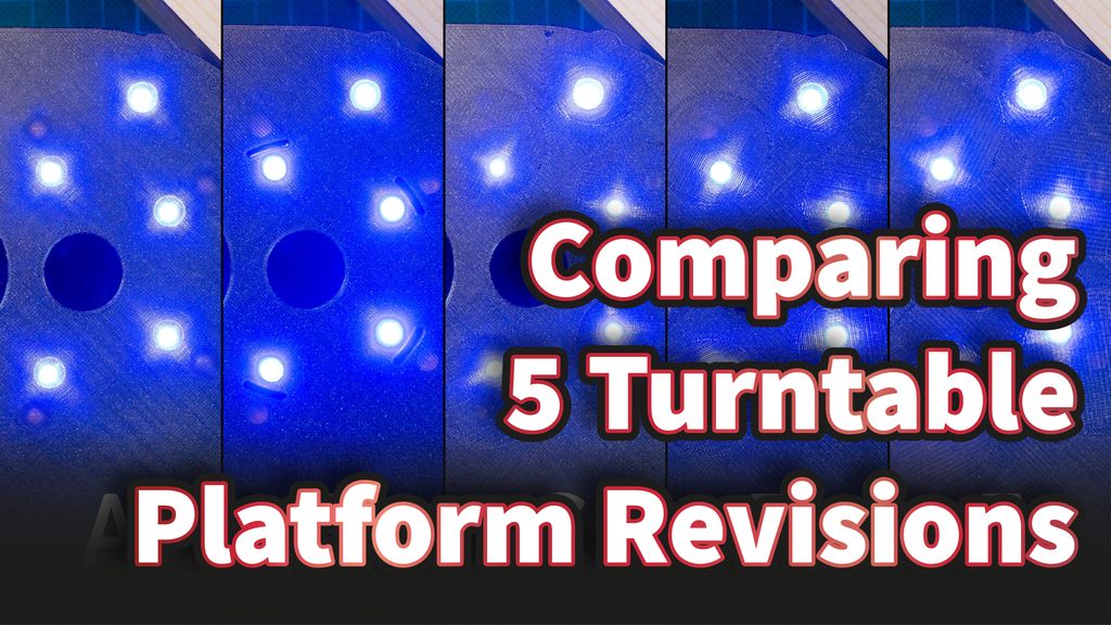
To solve the problem with light inference, I tested five different revisions of the turntable platform. For each revision, I recorded the sensor values and compared them to find the best solution.
Table of Contents
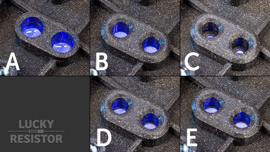
Visual Comparison
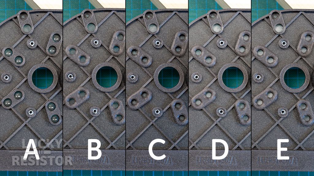
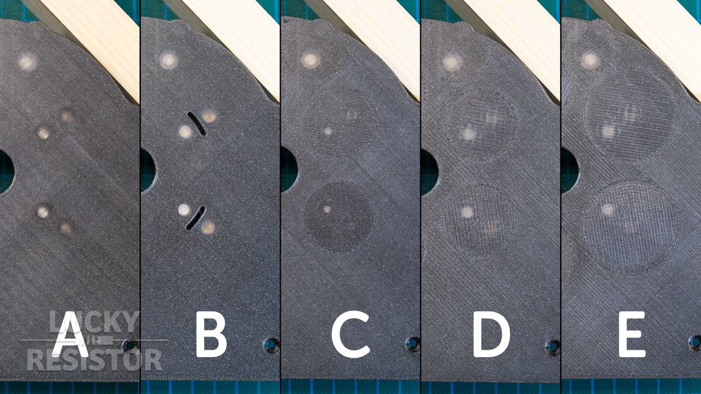
Revision A is the original with the light inference problem. In the text, I describe only the differences to this original version.
Bottom side, revision B-E: I reduced the diameter of the opening to increase the width of opaque material between the LED and the phototransistor.
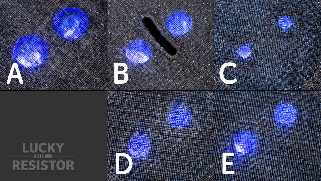
Surface:
Revision B1: An empty slot separates the transparent layer between LED and phototransistor. An empty slot separates the transparent layer between LED and phototransistor.
Revision B2: Like B1, but the slot is filled with opaque epoxy. Like B1, but the slot is filled with opaque epoxy.
Revision C, D: The orientation of the printed lines is 45º to the line between LED and phototransistor. The orientation of the printed lines is 45º to the line between LED and phototransistor.
Revision E: Like C and D, but increasing the diameter of the region where the line direction changes. Like C and D, but increasing the diameter of the region where the line direction changes.
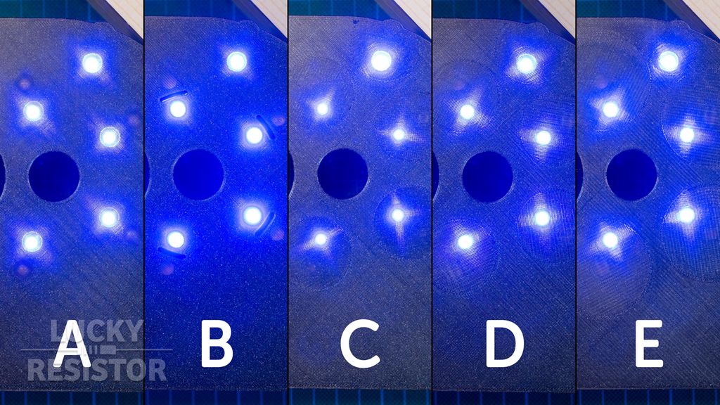
Visual Light Comparison: These images were made to compare the platform revisions using visual light. You can see how the angle of the printed lines influence how the light is distributed.
Openings Detail:
Revision B and E: The opening is smaller, but has no additional features. The opening is smaller, but has no additional features.
Revision C: The transmission area is reduced to a diameter of 3mm. The transmission area is reduced to a diameter of 3mm.
**Revision D: **The transmission area is reduced to a diameter of 5mm.The transmission area is reduced to a diameter of 5mm.
Printed Line Details:
Revision B: Regular print with the slot. Regular print with the slot.
Revision C: Angle of the lines is 45º to the sensor orientation. Angle of the lines is 45º to the sensor orientation.
Revision D: Like C, but with 0.6mm (larger than normal) line width on the first layer. Like C, but with 0.6mm (larger than normal) line width on the first layer.
Revision E: Larger adjustment area, 0.3mm (smaller than normal) line width on the first layer. Larger adjustment area, 0.3mm (smaller than normal) line width on the first layer.
Measurements
I repeated the exact same measurement for each platform at the exact same conditions:
All compartments empty with no lids.
All compartments empty with all lids closed. This is the This is the reference value, which is used as a calibration value for the sensors., which is used as a calibration value for the sensors.
All compartments filled with 30 pieces of test food, all lids open.
All compartments filled with 30 pieces of test food, all lids closed.
One compartment filled, all others empty, all lids closed.
I added the last test to check if measurements from one compartment influence measurements of other compartments.
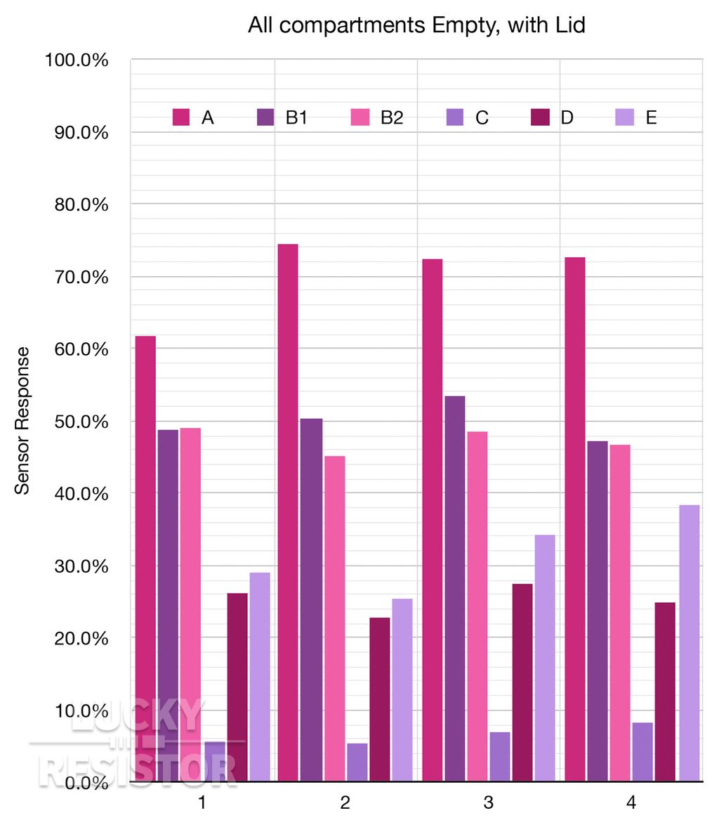
Empty Compartments
I use the measurement for a closed empty compartment as reference value. You can see, the original design has the highest response, because of the light inference problem. Revisions B1 and B2 have also a high response, but this is just the reflection from the lid.
The response of revision C is way too low, the diameter of the opening too small for good measurements. In increased the diameter in the next revisions and got better results.
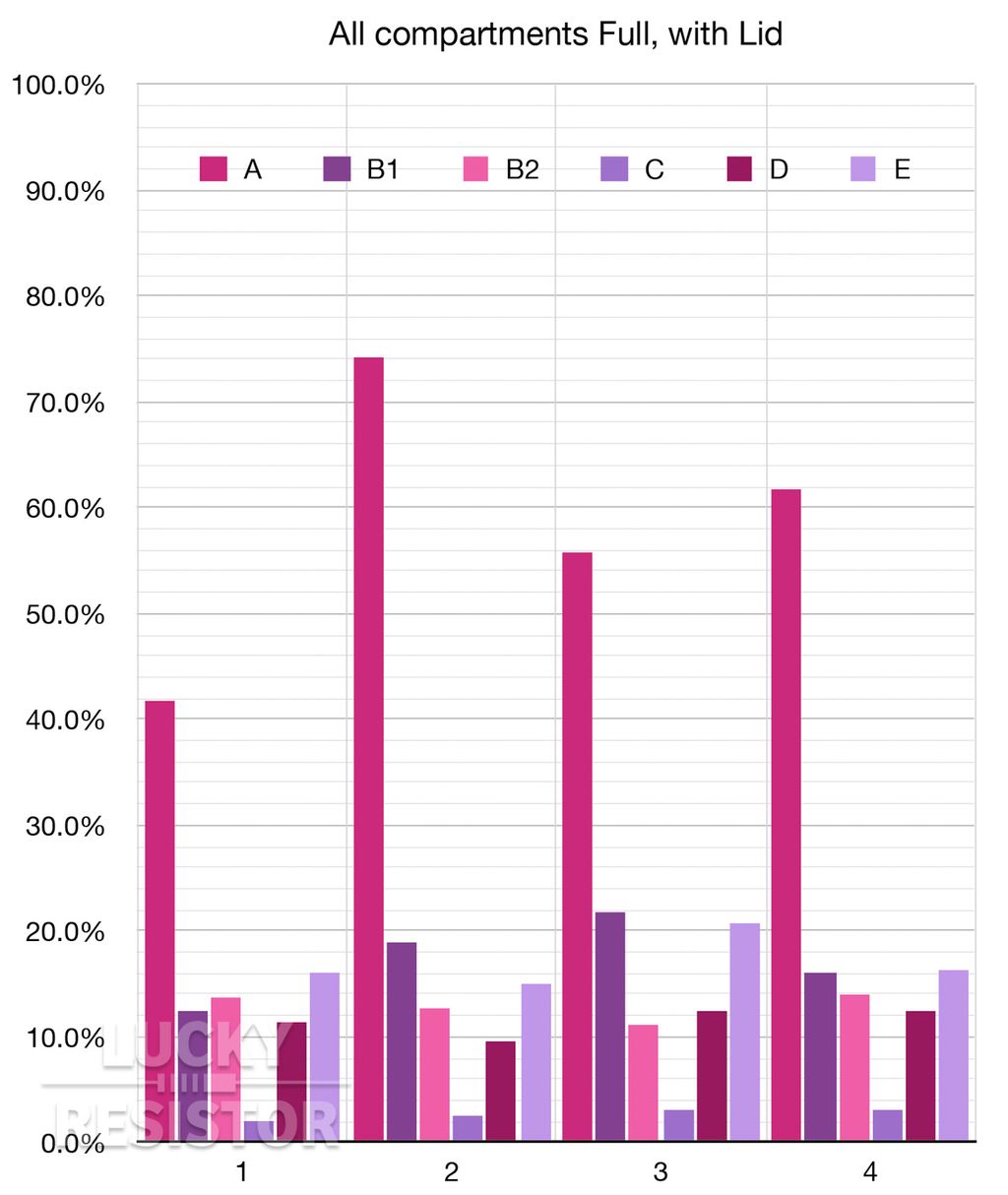
Full Compartments
In this diagram you clearly see the problem with the original design. The responses are really high, but they should be low, because the light is blocked by the food.
Delta Values Empty vs. Full
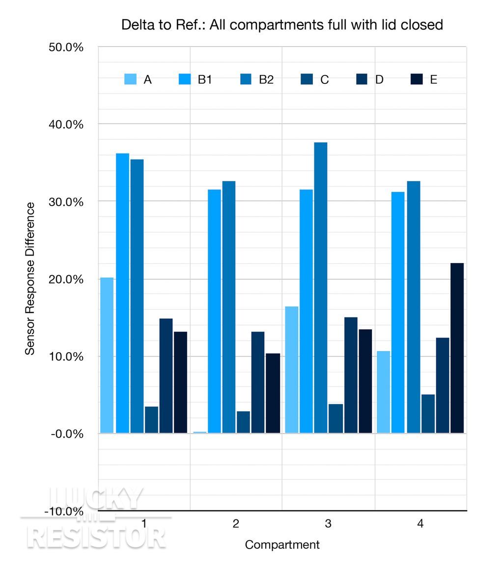
This diagram shows the difference between the empty and full measurement. A greater difference is better, because it makes the detection of a full compartment easier and more reliable.
Revisions B1 and B2 have the best results so far. Filling the slot with opaque epoxy has not the same effect on all sensors; it is again because the angle of the lines is different for each compartment in this revisions.
Revisions D and E have good results, but it is not as reliable as revision B. I repeated the tests for these revisions, refilling the compartment to randomise the particles in the chamber. For revision D, I got values between 10-16% and revision E between 10-25%.
On Patreon you will find all raw measurements, and full resolution images.
Conclusion
The revision with the slot between LED and phototransistor is the superior solution. The measurements are reliable and very distinctive. Yet, it requires some skill to apply the epoxy to this slot and is therefore not a solution for everyone.
Therefore, revision E is a valid alternative to this solution. A difference of a minimum of 10% may be acceptable for someone who likes to use the unmodified printed part.
Nikolay pointed out in a comment that sealing the printed parts using epoxy would be a sensible measure to make them food safe. He is absolutely right about this. If you are experienced using epoxy, sealing the printed parts for the final device is something you definitely should do.
In the pet-feeder series, I tried to keep everything as simple as possible so that most people can copy it. Therefore, I avoid working with epoxy, because it requires experience, preparation and patience and is not for everyone.
If you have any questions, missed information, or simply want to provide feedback, feel free to comment below. 😄
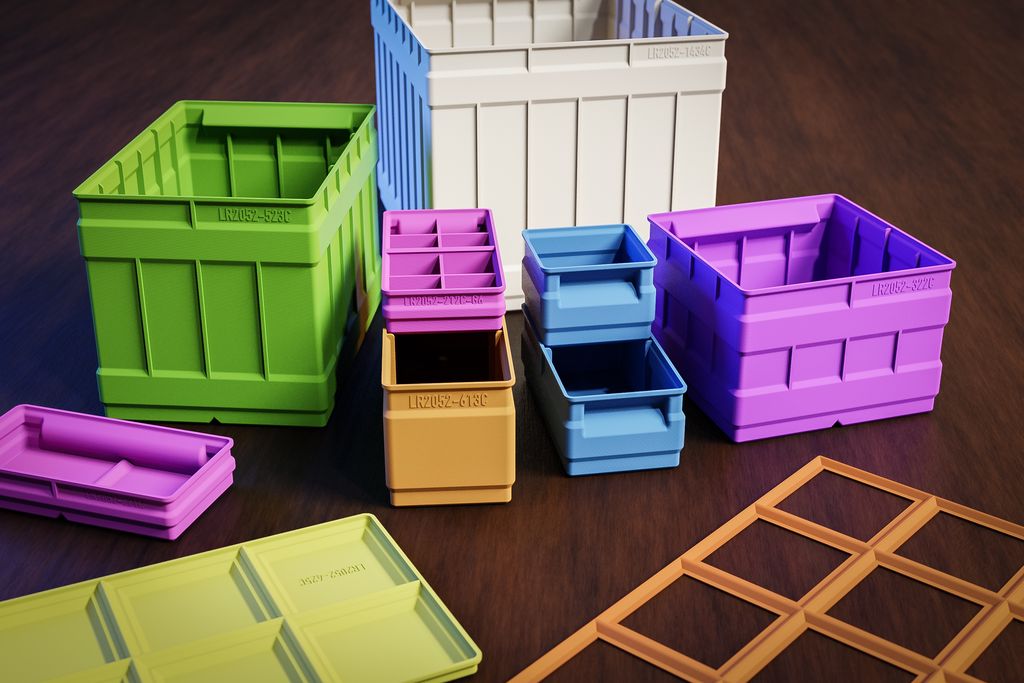
I recently updated my storage-boxes system to include split boxes so you can print larger containers or use small printer beds. I tested glued joints with PLA and PETG and added 12 new STL parts. Read the full post to see part numbers, joining tips, and where to download them.
I walk you through how I get camera-ready solder work: choosing the right iron and pliers, selecting solder and flux, careful prep, cutting and reheating for shiny domes, plus cleaning for macro photos. If you want neater prototypes or better product shots, read the full step-by-step guide.
I built a simple, modular CMake-based toolchain for Adafruit Feather M0 boards that reuses Arduino tools while giving full build control. It’s aimed at prototype work and HAL development on macOS and Linux. If you’re curious, read the full post for setup steps and examples.
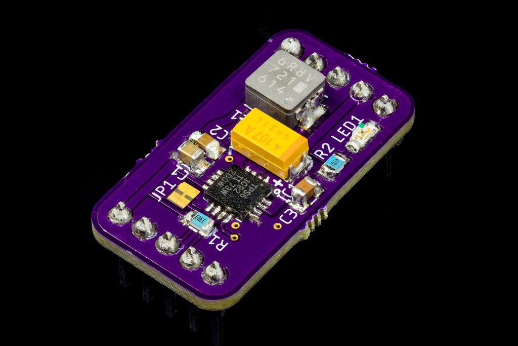
I built a small test board for the TPS61092 to evaluate thermal performance, hand‑solderability, and layout before using it in my project. The chip stayed cool under 0.5A and the OSH Park PCB looked great. Read on for measurements, the BOM, and practical soldering tips if you want to try it.
I’ve released a major update to my 3D-print storage box system: expanded sizes (up to 6x6 and 9x9 split), improved geometries, 3MF files, JPEG previews, and more dividers. If you use my boxes or print them yourself, read the full post for download links, compatibility notes, and printing tips.
I created a readable, fully inline AES‑256/CBC implementation you can drop into C++ projects — handy for embedded systems. It avoids static S‑Boxes, needs only stdint/cstddef, and is MIT‑licensed on GitHub. If this sounds useful, read the full post for requirements, example code, and usage notes.