published: March 31, 2021 —
last modified: October 23, 2025
While testing the sensor panel, I ran into unexpected problems, requiring a small redesign.
Table of Contents
First, let me explain the simple working principle of the fill sensor circuit and what I tested so far.
The Circuit
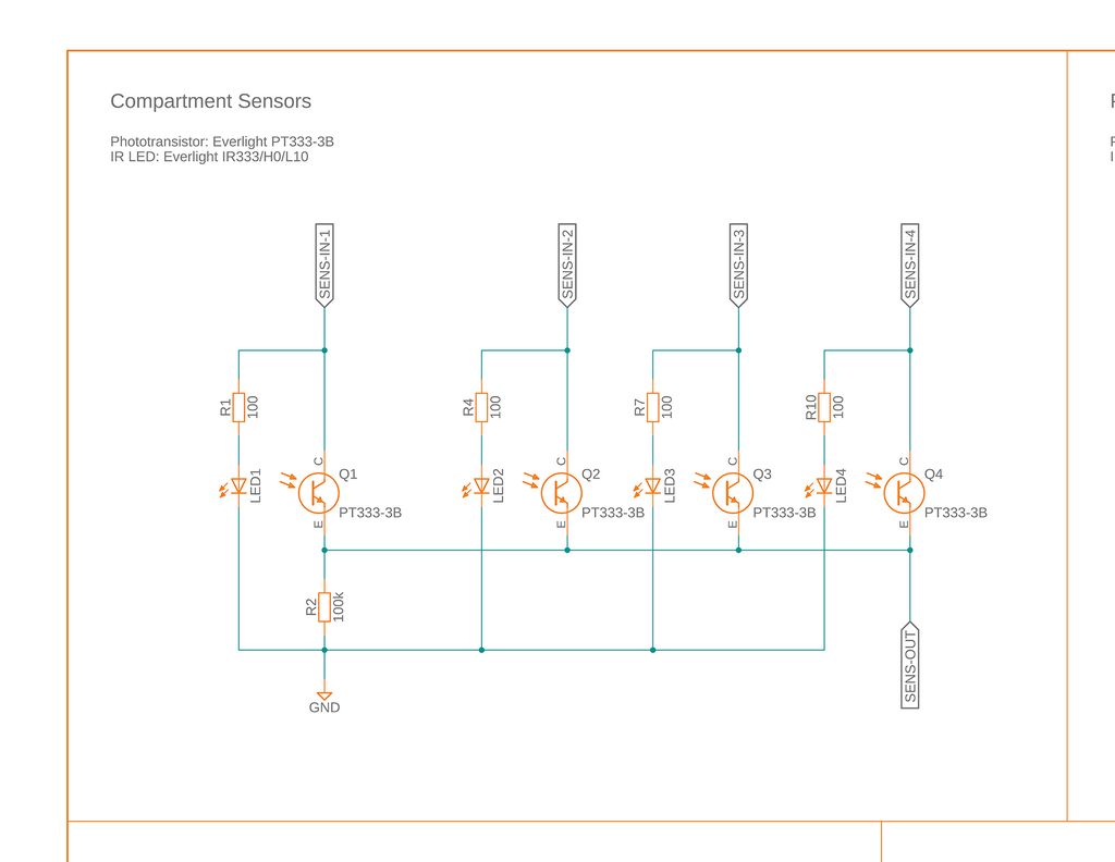
The circuit for the fill sensors is straight forward. There are four input lines and one analogue output line. If a voltage is applied to one of the input lines, the IR LED for one compartment is lighting up.
Mode of Operation
If the compartment is empty, the light reflects from the white lid, back to the IR transistor in the middle. In this case, you read a higher voltage on the output line.
If there is food in the compartment, the light is blocked, and you read a lower voltage.
It is not a foolproof system, because it relies on the lid on top of the compartment and it will probably not work with every kind of food. Therefore, adding a visual feedback on the display will play an important part in the usability of the system.
First Tests
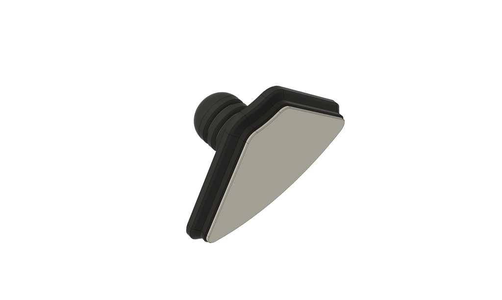
After the first tests, I realised the reflections from the lid were not distinctive enough - most likely because the lid is black. As a quick solution I designed a cap, which is inserted into the lid and provide a flat reflective surface for the sensor.
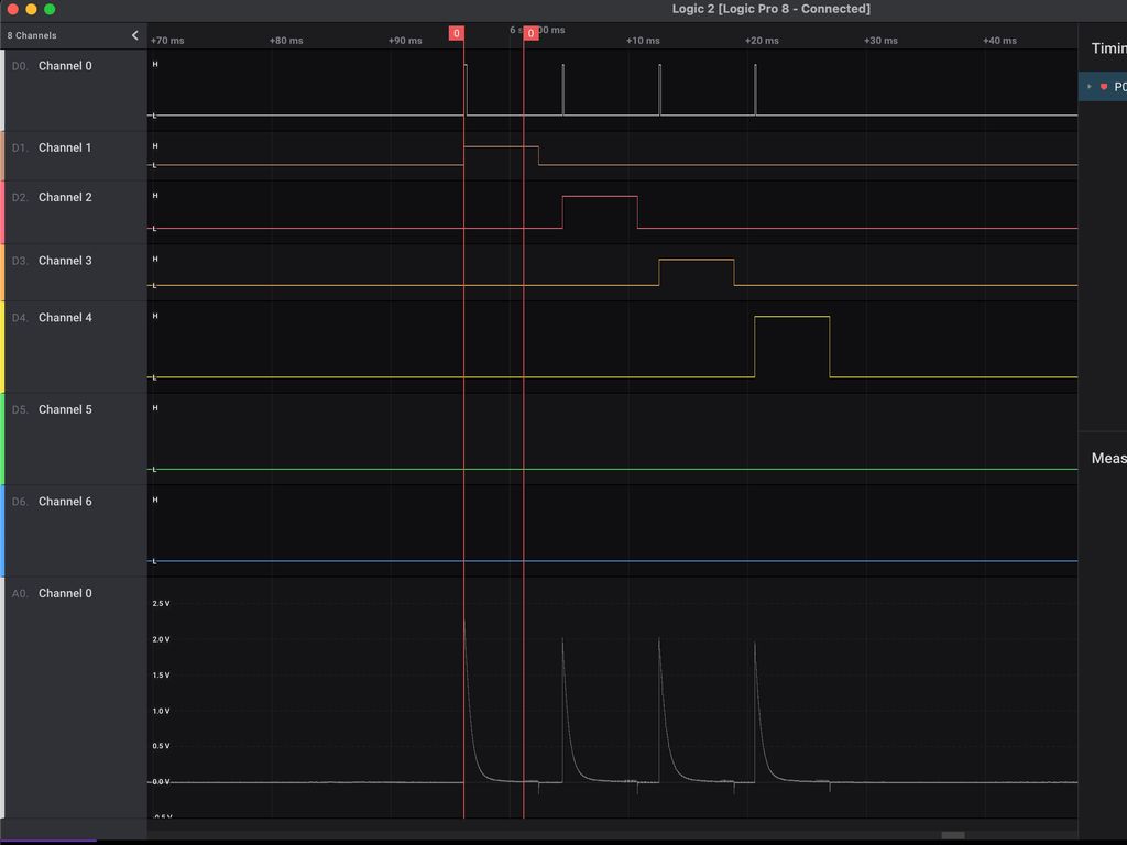
Each sensor is tested in turn and a number of readings from the ADC are interpolated. The resulting value is then compared to a reference value of a known empty compartment.
Here you can see how the sensor readings for four full compartments look like. After turning the power on for one channel, there is a spike until the phototransistor is stable. This is one point I have to investigate. After 50ms, I measure the voltage multiple times and switch to the next channel.
Analysing Responses
I took readings of the empty compartments and stored them as base values. This is a calibration, which has to be done manually or automatically over time.
Readings of empty compartments.
0:bc67
1:c028
2:bd9a
3:be01
After setting the base value, I am just interested in the difference.
So, while I get a distinctive difference for three compartments, the fill sensor for the second compartment read almost the same value. If you look at the initial readings, the second sensor has a higher value compared to the other sensors.
Searching the Problem
To eliminate a problem with the LEDs or IR Transistors, I assembled an identical sensor board and used this copy. Here I got exactly the same issue. After I eliminating all other problems, the issue must have beed caused by the turntable platform itself.
I carefully examined the locations of each sensor, but could not see any difference between them. Then, I had to idea to use visual light…
An Unexpected Cause for the Issues
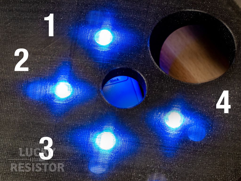
The following photo montage illustrates the problem:
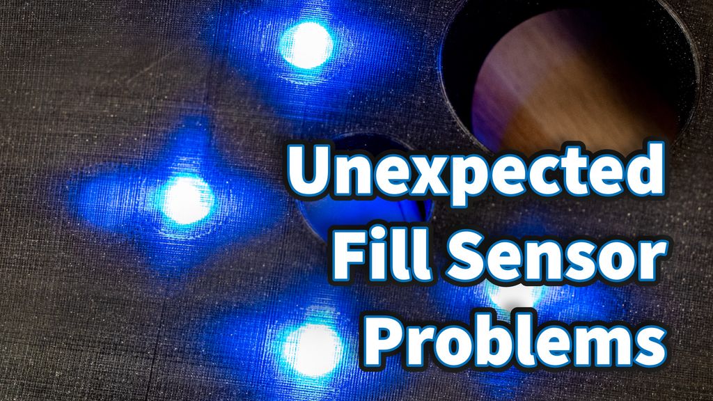
As you can see, the light follows the lines of the printed part. In slot one and four, the sensor is in the “shadow” of the light distribution. Also, the angle on slot three seems to be different enough to cause no problems. The sensor of slot two, in the path of the light distribution. This sensor seems to get light from the LED through the transparent surface of the platform.
Solutions that did not Work
Inserting an additional part into the sensor or LED holes to reduce the diameter of the input or output did not work.
Changing the distance of the LEDs and sensors from the transparent window did not work.
Using tape to reduce the output and/or input angle of the LED and sensor did not work.
It seems, the light is transported along the printed material so well, it outshines any actual input from the chamber.
Solutions Currently Investigated
So, the bad news is, if you already printed the turntable platform and like to use the fill sensor - most likely have to reprint it. My apologies about this! 😔
Adding a Slot
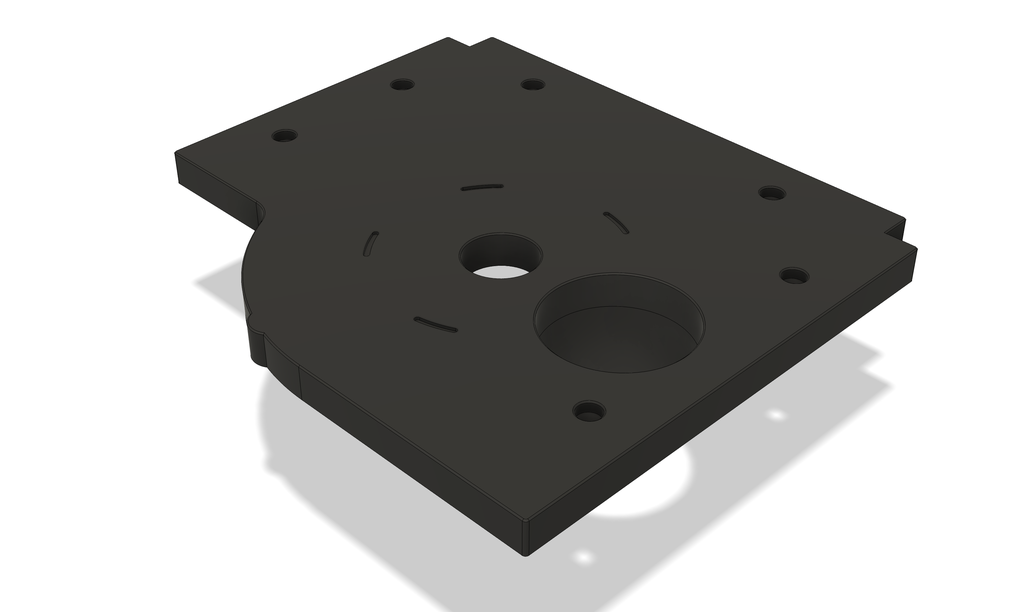
One of the simplest solutions seemed to add a slot between the sensor and LED. This slot has to be filled with something food-safe opaque. I am currently testing epoxy resin and acrylic paint. There are a number of disadvantages:
Not everyone is able to precisely fill this slots with epoxy or acrylic paint.
The surface isn’t perfectly flat anymore - harder to clean.
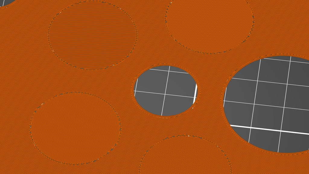
Adjusting the Fill Pattern
An even simpler solution could be adjusting the infill angle in each sensor area as shown above. It could have a positive effect on the sensor reading because each field has exactly the same amount of error. There are two disadvantages:
Adding custom infill directions requires advanced slicer knowledge. I can provide a slicer profile for the Prusa Slicer, but I have no clue if this is possible with other slicers as well.
Because of the different fill orientations, there will be a small gap between all the layers. I don’t know, how well the print will turn out using this technique.
Conclusion
At the moment I am printing the new platforms to compare the results. As soon I can do some tests, I can decide which solution is the best.
I hope you found this update about the tests and fill sensor problems interesting. If you have any questions, missed information, or simply want to provide feedback, feel free to comment below or contact me on Twitter. 😄
I built a PID-controlled fan and temperature controller for my printer enclosure in about four hours using an Adafruit Feather, DHT22, OLED, MOSFET, and a PWM fan. I walk through printing the case, wiring, firmware setup, and assembly—read on if you'd like to build one yourself.
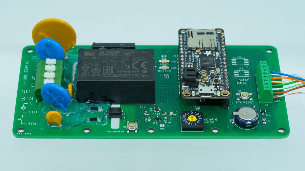
I recently built 'Always-On', a minimal bidirectional mains-to-Feather bridge combining a power sensor and solid-state relay for safe home-control prototypes. I outline design choices, safe firmware testing without mains, and housing tips. If you're exploring a similar controller, read the full post for a practical starting point.
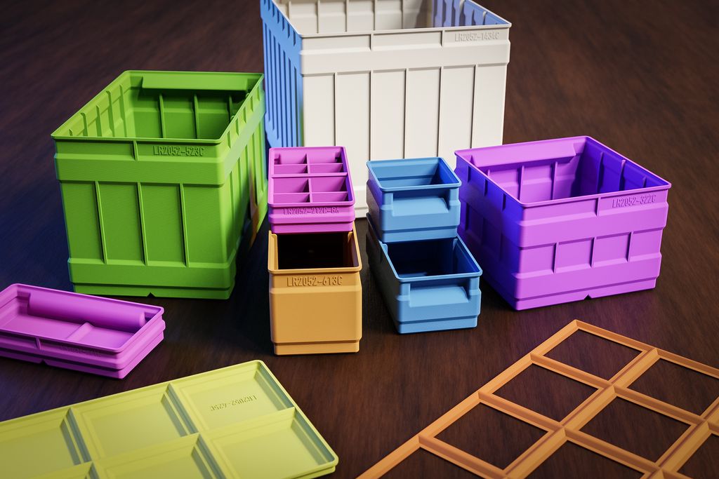
I've added a batch of new divider layouts across my storage box system — regular, flat, tall, triple and extended series — based on your feedback. I've updated documentation and uploads; downloads are available on the new platform. Please take a look and read the full post for details and download links.
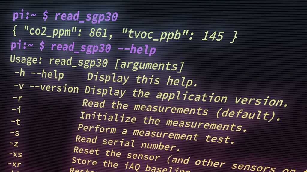
I published a small command-line tool to read the Sensirion SGP30 air-quality sensor on a Raspberry Pi. I explain usage, options, and how to build and install the C tool so you can get JSON CO2/TVOC output. If it helps, please read the full post for details.
I’ve released a major update to my 3D-print storage box system: expanded sizes (up to 6x6 and 9x9 split), improved geometries, 3MF files, JPEG previews, and more dividers. If you use my boxes or print them yourself, read the full post for download links, compatibility notes, and printing tips.
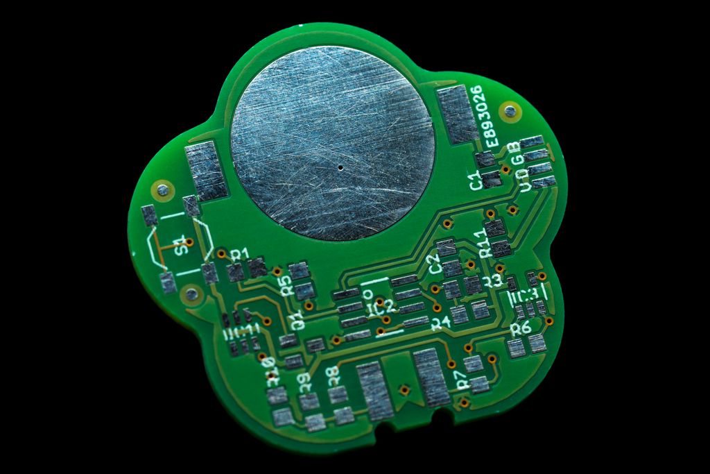
I walk you through designing the final PCB for a low-cost plant watering sensor: choosing tools, shaping the board, iterative layouts, BOM decisions, assembly planning and unit-cost calculations. If you want practical steps and cost details, please read the full post to follow the next parts.