published: March 22, 2021 —
last modified: October 23, 2025
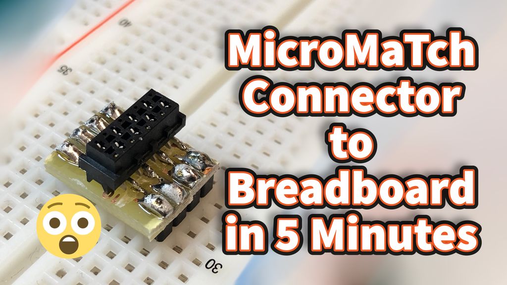
Ordering a board with perfect spaced pads to use an SMD connector takes a few days of patience unless you live near a PCB prototyping facility. With striped prototyping boards, you can stick a MircoMaTch or similar connector into your breadboard in under five minutes. 😉
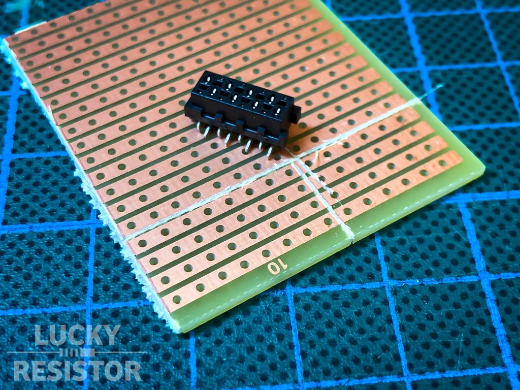
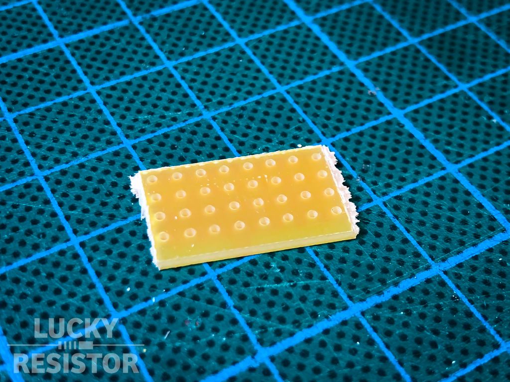
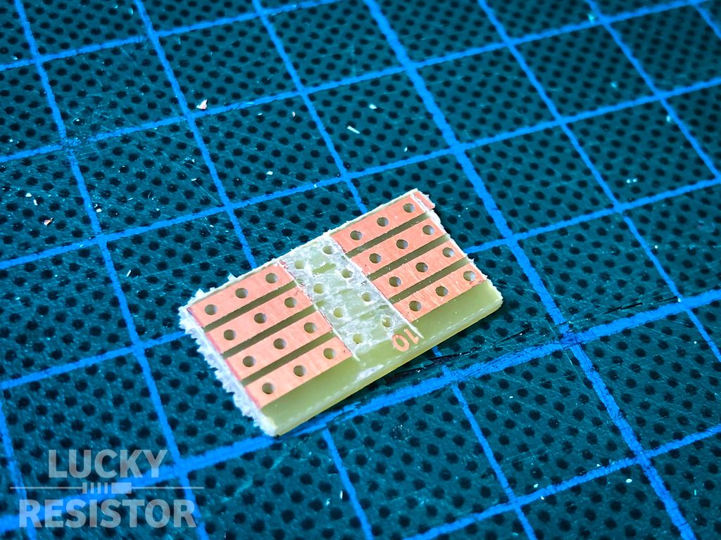
First cut a small piece from the prototype board. I use a paper knife, scratching groves using a ruler at the right locations and break the board using pliers.
It’s messy, but the board breaks more or less along the right locations.
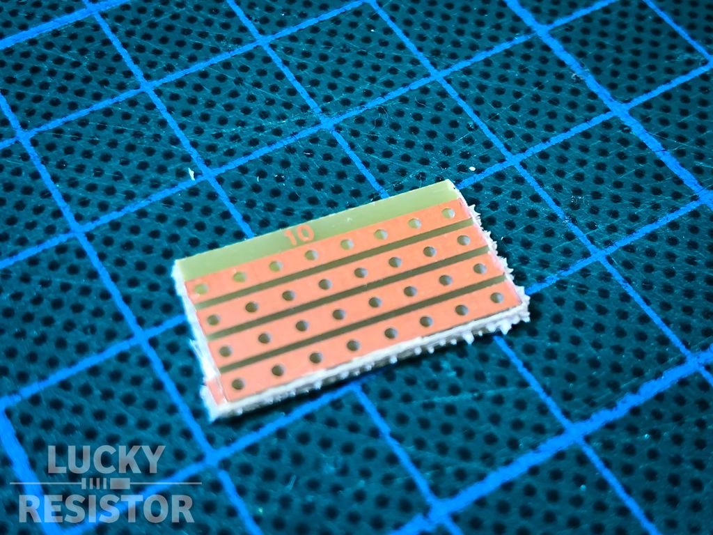
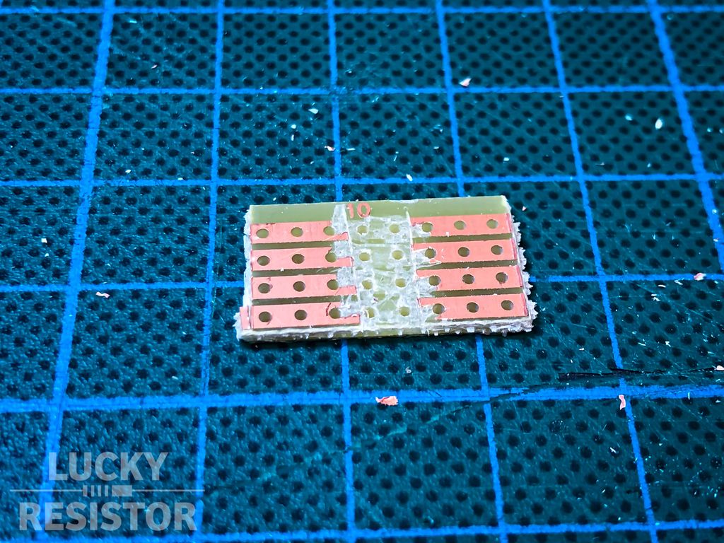
Next we need to remove the middle section. The stripes must not be connected.
With the paper-knife, I first cut the stripes, then scape the copper from the board. It’s like cutting thin slices from smoked salmon (google instructions): You need a flexible knife, moving it flat under the copper layer. With four such cuts, the middle part is removed and copper free.
Now the tricky part: Because of the 0.1 inch spacing of the connector, you have to remove half of each stripe on each side. I use the hole as a starting point for two small cuts, then scraping the copper away. After this step, I use a loupe to check if all copper is removed and there are no shorts.
Before start soldering, clean all the copper dust from the mat and board.
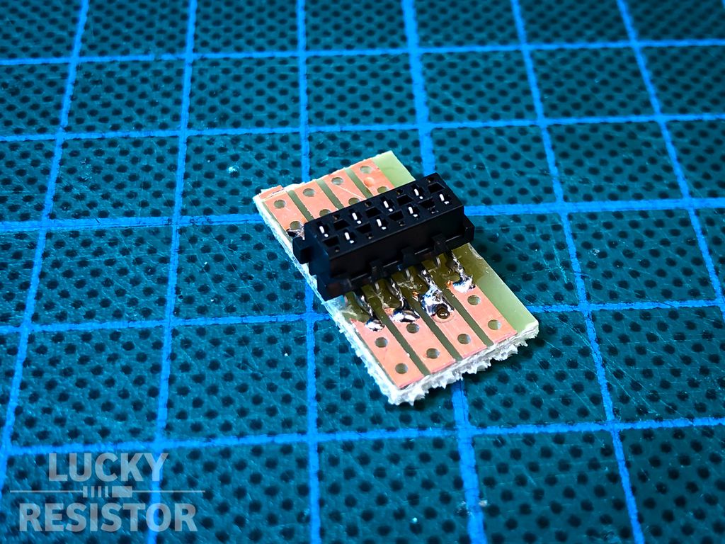
Soldering is simple, carefully keep the holes near the connector open for the pin header.
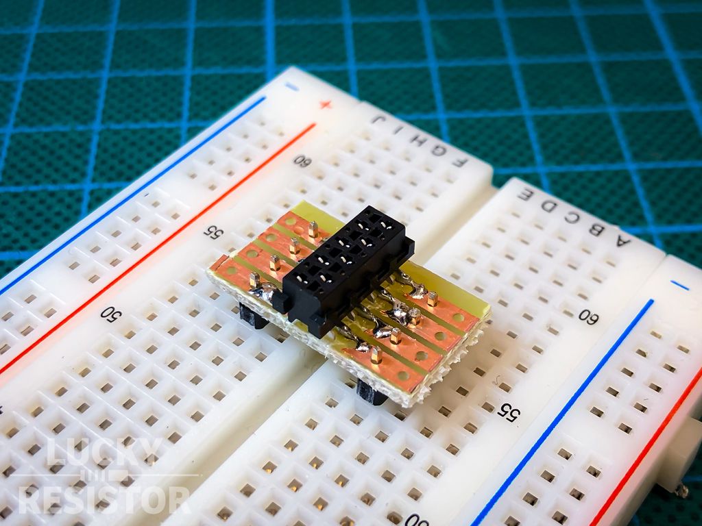
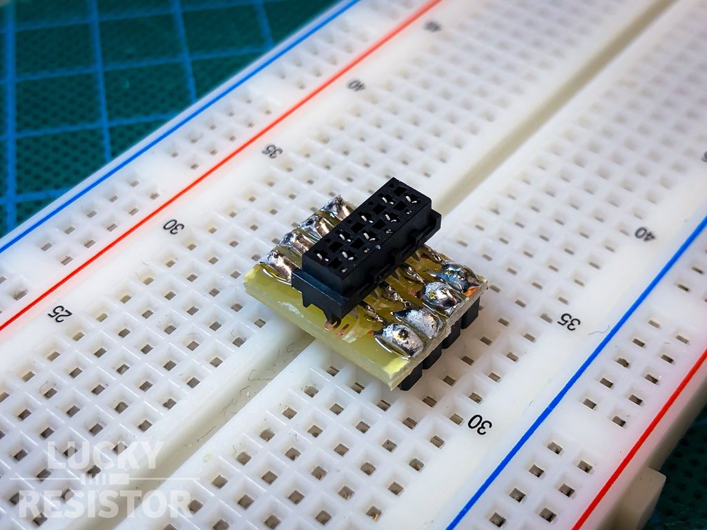
Next, insert the pin header into a breadboard and put the prototype board with the connector on top.
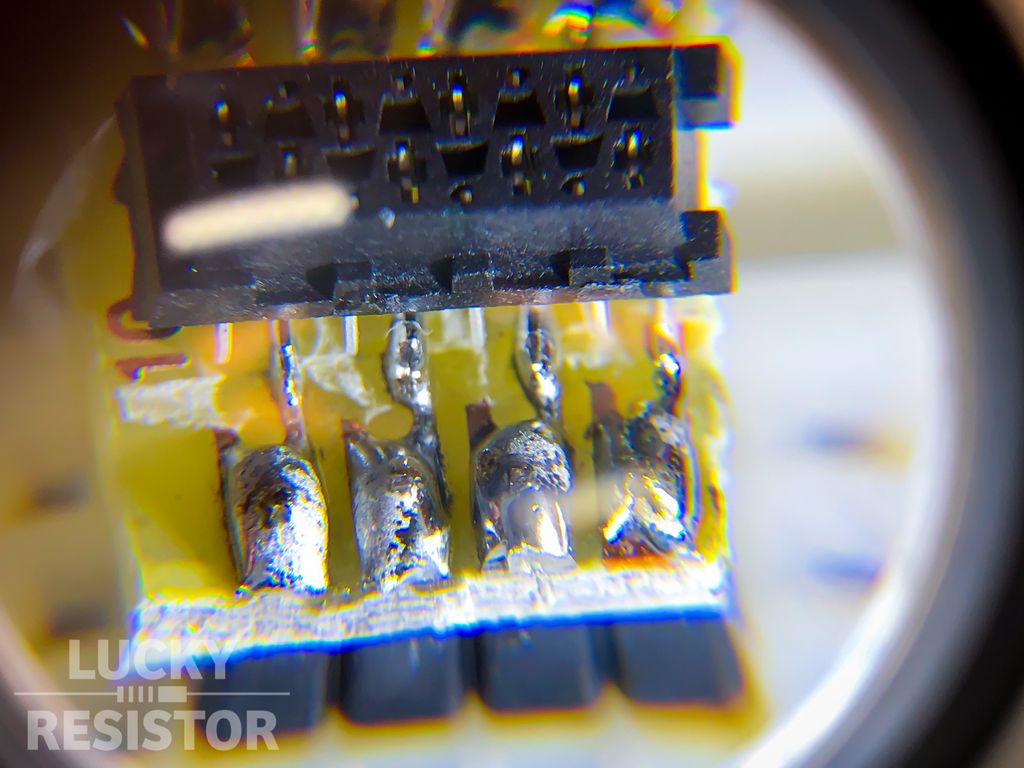
After soldering the pins to the board, I check with a loupe if everything is connected, ideally with a line of solder.
I use a side cutter to remove any excess sections of the board to make the adapter as compact as possible.
Done! 🎉😅
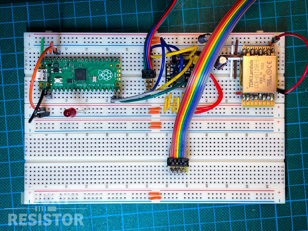
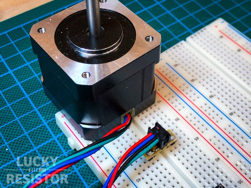
Now I can connect the device to the breadboard with style, but you may ask:
Why using a connector instead of single wires for testing?
If you build larger projects using multiple small dedicated boards you have to connect them. Soldering ribbon cables into place make only sense if you never plan to ever disassemble or repair a device. Adding connectors to the boards makes repair and testing easy.
In an extreme case, you can start building every module of your device using breadboards and use the final connectors connecting them. Now, you can start replacing module by module with soldered prototype boards or manufactured boards.
Because you have the connectors and ribbon cables, you can easily interchange modules just by reconnecting them. It is an easy way to switch between e.g. the breadboard version of a module and the final version to see if they behave correctly.
Conclusion
I hope this article gave you some inspiration, and motivation to use more connectors in your projects. 😄
If you have any questions, missed information, or simply want to provide feedback, feel free to comment below or contact me on Twitter. 😄
Posted on 2019-07-13— C++, Improve your Code, Learn
I explain why I prefer #pragma once over macro header guards and how it prevents subtle build errors and wasted debugging time. I’ll show examples, common pitfalls, and practical steps to replace guards in existing projects — read on if you want a simple, low-risk improvement.
I'm happy to share you can now buy an assembled Snowflake Decoration from Pimoroni with worldwide shipping. The panels arrive pre-soldered, use 5V power and flat cables so no soldering is needed. If you'd like details on the updates and compatibility, please read the full post.
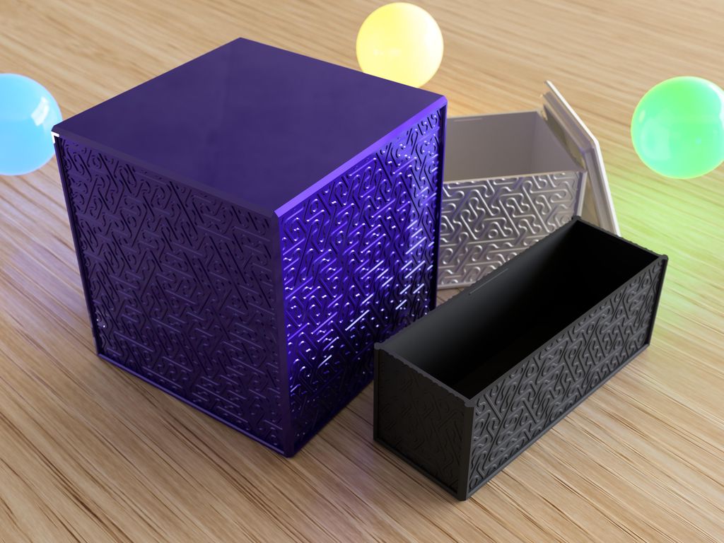
I created a set of 500 printable boxes with a random line pattern—each box unique, sized 35–120 mm with two lid fits per size. I cover part naming, printing tips, and where to download the STLs. If you use 3D printing, please read the full post for files and guidance.
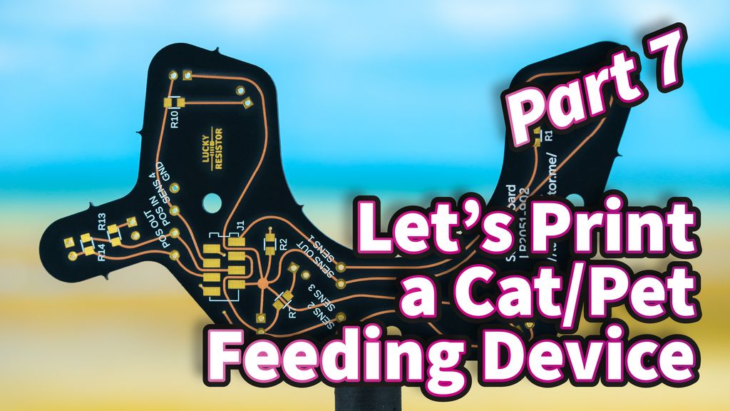
I walk through the sensor board I designed for the pet feeder, explaining the position sensor, four fill sensors, and why component choices (like the 100kΩ resistor) matter. I keep the design simple and practical — read the full post for schematics, measurements, and ordering details.
I received 3mil polyimide stencils from OSH Stencils for my Swiss precision timer project. They feel flimsy compared to the steel stencils I usually use, but cost much less. I’ll test solder paste application and the first prototype in the coming weeks — please read the full post for results.
I created a symmetrical logic‑gate diagram and challenge you to spot its function. Study the image, try simplifying the design, and use the provided hints if needed. If you enjoy puzzles or digital logic, read the full post for extra challenges and to compare solutions.