published: March 21, 2021 —
last modified: October 23, 2025
I worked on testing the sensor board. The first tests I did were about the position sensor.
Table of Contents
Recap
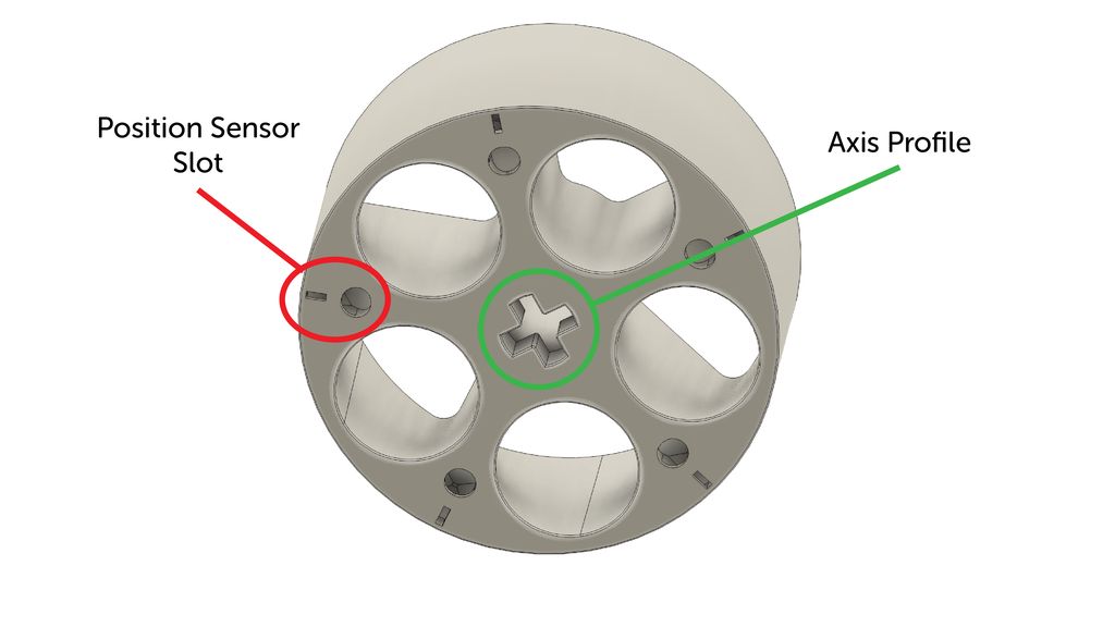
Let me recap the design of the position sensor in the device: The turntable has five position slots, marked red in the following illustration.
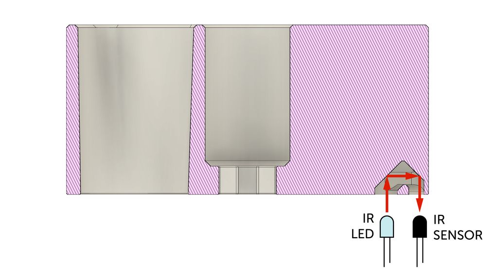
Behind this slots, there is a small excavation, reflecting the light from the infrared LED to the phototransistor.
Circuit
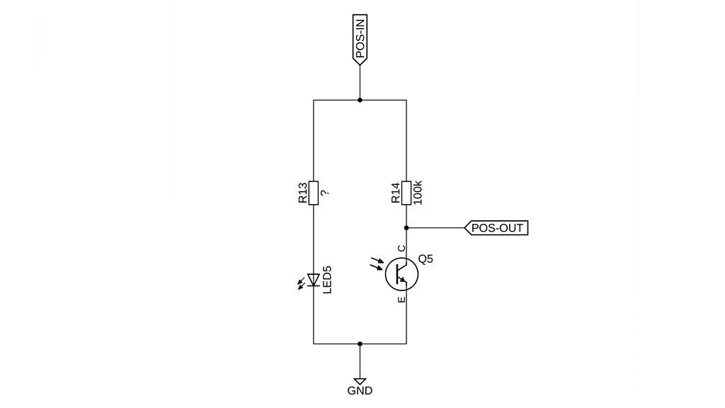
The circuit, with the LED and the phototransistor is shown in the following circuit diagram:
There is a line POS-IN and POS-OUT connected to the microcontroller. The idea is to keep this circuit without power if it isn’t used. As soon 3.3V is applied to POS-IN, the infrared LED lights up, and the voltage divider between the resistor R14 and the phototransistor, gets a working voltage. Therefore, POS-OUT gets a voltage between VCC and GND.
More light on the phototransistor will conduct more current to GND, therefore the voltage will drop. So, the resistor R14 controls the sensitivity of this detector.
First Measurement
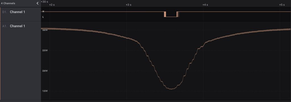
I started with a 10kΩ resistor, which was a too strong pull-up, so I changed it into a 100kΩ resistor. Here you can see the first measurement I did, rotating the turntable at a slow speed.
The signal is between 3.0V and 1.5V, which is perfect for the task. The response curve is very smooth, so it is easy to set a trigger point to get the correct timing for the rotation.
Controller Setup with MicroPython
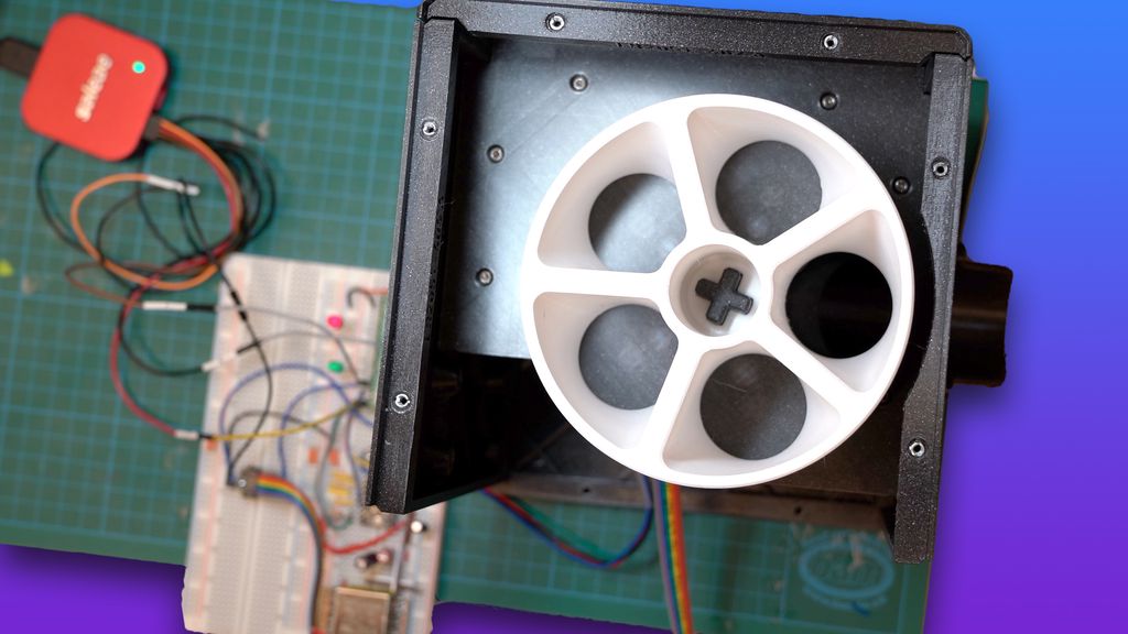
I set up a microcontroller with a stepper driver and connected it to the motor and position sensor. As a microcontroller, I used a Raspberry Pi Pico. The stepper driver is not the final one, I need to test a few more, less noisy drivers. 😄
In MicroPython I wrote simple test code for sensor readout, interpolation and calibration:
frommachineimportPin,PWM,ADCimportutimestepper_sleep=Pin(13,Pin.OUT,value=0)dir_pin=Pin(15,Pin.OUT,value=0)step_pwm=PWM(Pin(14))pos_sens_out=Pin(12,Pin.OUT,value=0)pos_sens_in=ADC(26)trigger_sensor_value=0x9500defread_pos_sensor()->int:pos_sens_out.value(1)utime.sleep_ms(5)sensor_sum=0sensor_samples=const(16)for_inrange(sensor_samples):sensor_sum+=pos_sens_in.read_u16()utime.sleep_us(100)pos_sens_out.value(0)returnsensor_sum//sensor_samplesdefis_at_position()->bool:returnread_pos_sensor()<trigger_sensor_valuedefstart_turntable():stepper_sleep.value(1)utime.sleep_ms(10)dir_pin.value(0)utime.sleep_ms(10)step_pwm.duty_u16(0x8000)step_pwm.freq(500)forfreqinrange(500,5000,100):step_pwm.duty_u16(0)step_pwm.freq(freq)step_pwm.duty_u16(0x8000)utime.sleep_ms(10)step_pwm.freq(5000)defstop_turntable():step_pwm.freq(100)step_pwm.duty_u16(0)utime.sleep_ms(10)dir_pin.value(0)stepper_sleep.value(0)defmove_turntable_one_slot():print('Start turntable')start_turntable()ifis_at_position():print('It is at position, wait until we leave')whileis_at_position():utime.sleep_ms(10)print('Wait for the next position')whilenotis_at_position():utime.sleep_ms(10)print('Stop the turntable')stop_turntable()deftest_speeds():stepper_sleep.value(1)utime.sleep_ms(10)dir_pin.value(0)utime.sleep_ms(10)forfreqinrange(100,10000,100):print(freq)step_pwm.duty_u16(0x8000)step_pwm.freq(freq)utime.sleep_ms(100)step_pwm.freq(100)step_pwm.duty_u16(0)utime.sleep_ms(10)dir_pin.value(0)stepper_sleep.value(0)defcalibrate_pos_sensor():print('Record max and min for 10 seconds')max_value=0x0000min_value=0xffffstart_turntable()end_time=utime.ticks_add(utime.ticks_ms(),10000)whileutime.ticks_diff(utime.ticks_ms(),end_time)<0:sensor_value=read_pos_sensor()max_value=max(max_value,sensor_value)min_value=min(min_value,sensor_value)utime.sleep_ms(50)print('Calibration finished.')print('Min: 0x{:04x} Max: 0x{:04x}'.format(min_value,max_value))print('Suggested trigger: 0x{:04x}'.format(min_value+(max_value-min_value)//2))stop_turntable()move_turntable_one_slot()
Video
The following video shows the controller in action. The turntable precisely turns to the next slot. I expected I need to add calibration, where I can add a number of steps after the position sensor gets triggered. But the readout is clean enough, to work without additional movement. If I stop the motor exactly at the trigger point, the slot is perfectly aligned with the output funnel.
You can hear the original sound of the motor with the current stepper driver. It is way too loud for this device. Hopefully, drivers with higher PWM frequencies will drive the motor with less noise.
Conclusion and Prospects
The position sensor on the board works flawlessly and way better than expected. Next, I test the sensors for the compartments. Here, I expect I need some small changes on the lids, adding a white part for better reflection.
If these tests are successful, I will publish the next part in the pet-feeder series, with all details and sources about the sensor board.
I hope you found this update about the tests interesting. If you have any questions, missed information, or simply want to provide feedback, feel free to comment below or contact me on Twitter. 😄
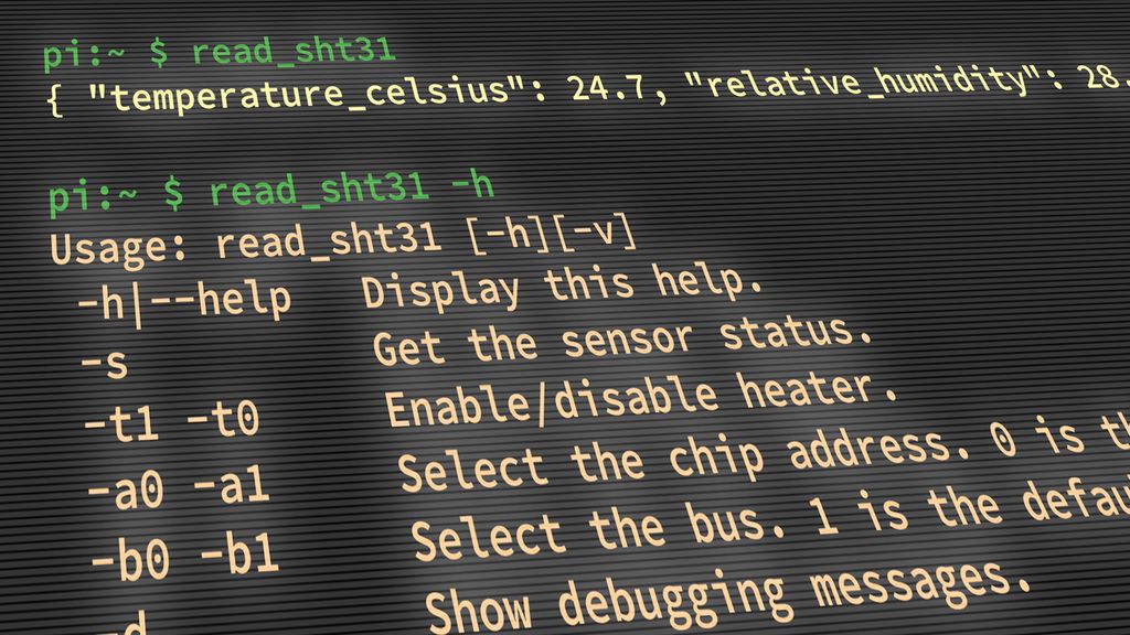
I built a small compiled command-line tool to read SHT31 temperature and humidity over I2C on a Raspberry Pi. It emits simple JSON for easy parsing in scripts. If you're using an SHT31 sensor or automating reads, read the full post for usage, build and install steps.
I walked through designing and 3D-printing a 70 cm PETG planter for my deep-rooted Ctenanthe. I share the tests, design choices, and practical fixes for warping, filament, split parts, and assembly. If you’re curious about large-scale prints or want the model files and tips, please read the full post.
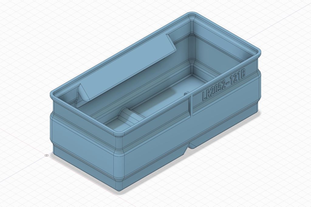
I've released several new 3D-print storage boxes with the label area moved to a different side so identical boxes can sit in a drawer with labels aligned. I explain size variants, rib adjustments, and how to download updated files. Please read the full post to see illustrations and the catalog link.
I walk through creating custom wiring for the snowflake decoration, covering layouts, cable choices, current and voltage-drop math, and a simple power supply board for Pimoroni kits. If you want practical tips and diagrams to wire your own design, please read the full guide.
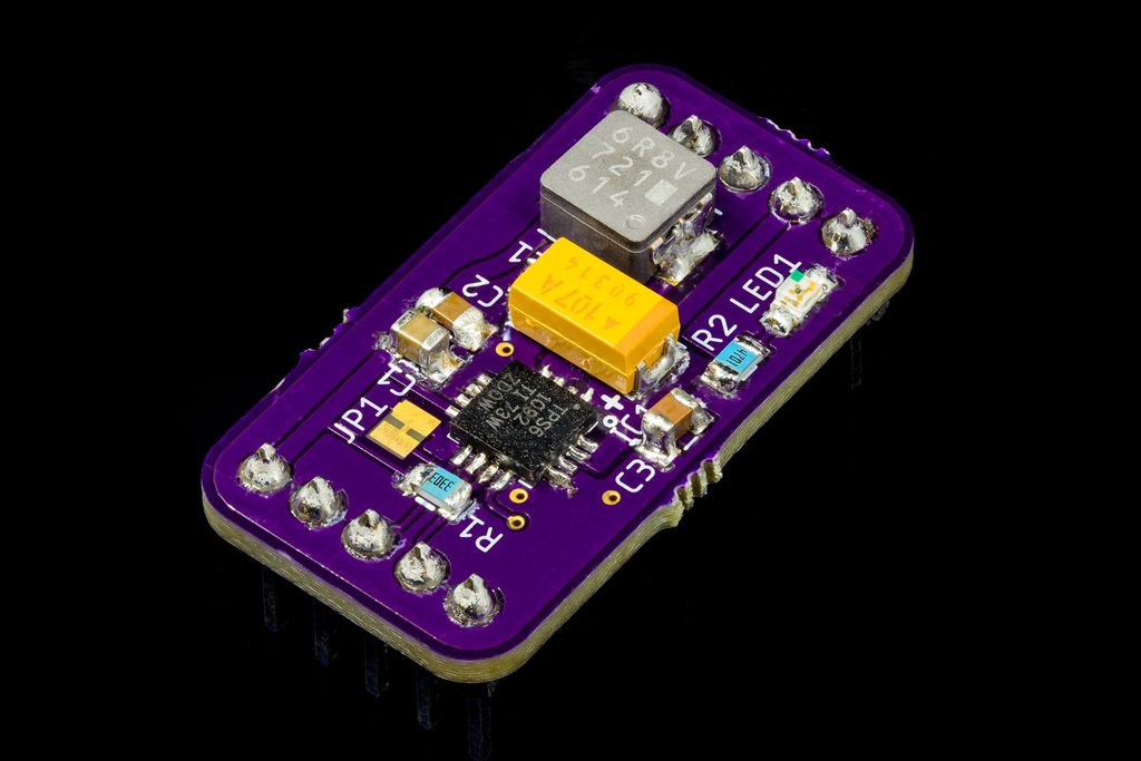
I built a small test board for the TPS61092 to evaluate thermal performance, hand‑solderability, and layout before using it in my project. The chip stayed cool under 0.5A and the OSH Park PCB looked great. Read on for measurements, the BOM, and practical soldering tips if you want to try it.
Posted on 2022-09-04— C++, Improve your Code, Learn
I take you on a short, pragmatic journey into C++ integer pitfalls—why signed and unsigned types behave oddly, how literals, negation and overflow can bite, and simple tests to reveal compiler quirks. If you work in embedded or systems code, please read the full post for examples and guidance.