published: March 14, 2021 —
last modified: October 23, 2025
When I migrated several servers into a new server rack, I put my Arduino Uno based fan controller into a new enclosure. Not a great solution, but good recycling of this existing project and way better than the built-in, on/off temperature controller.
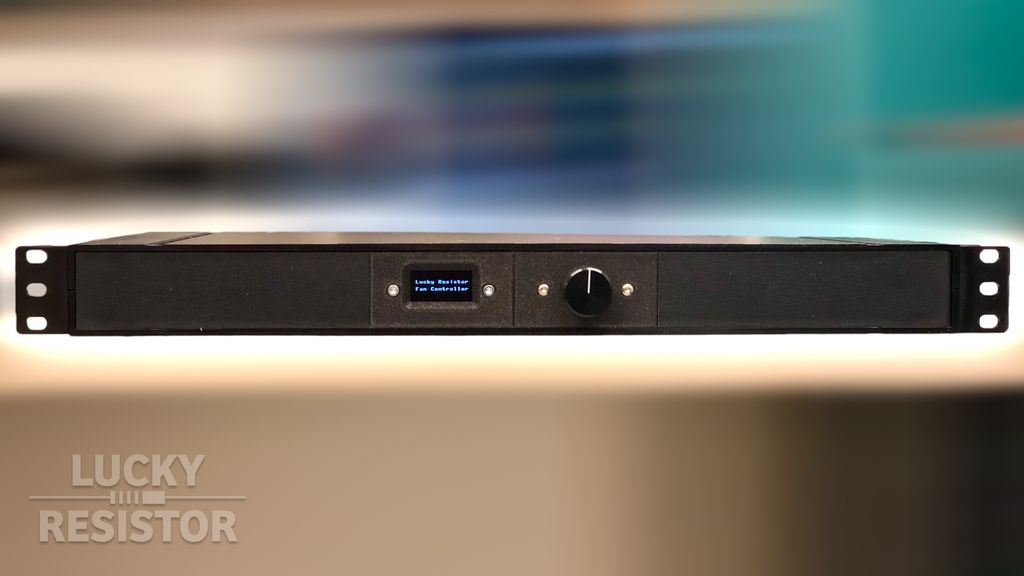
Now, when the rack’s space got low, I had to find a better solution, fitting in one single height unit. Obviously, I had to create something new; just buying an existing controller would have been boring. 😄
Table of Contents
The New Enclosure
Distrelec has a wide range of affordable enclosures of its own brand RND. I found the enclosure “RND 455-00114” would fit all my requirements, and with the price of ~16€, my solution could get even cheaper than a good off-the-shelf solution.
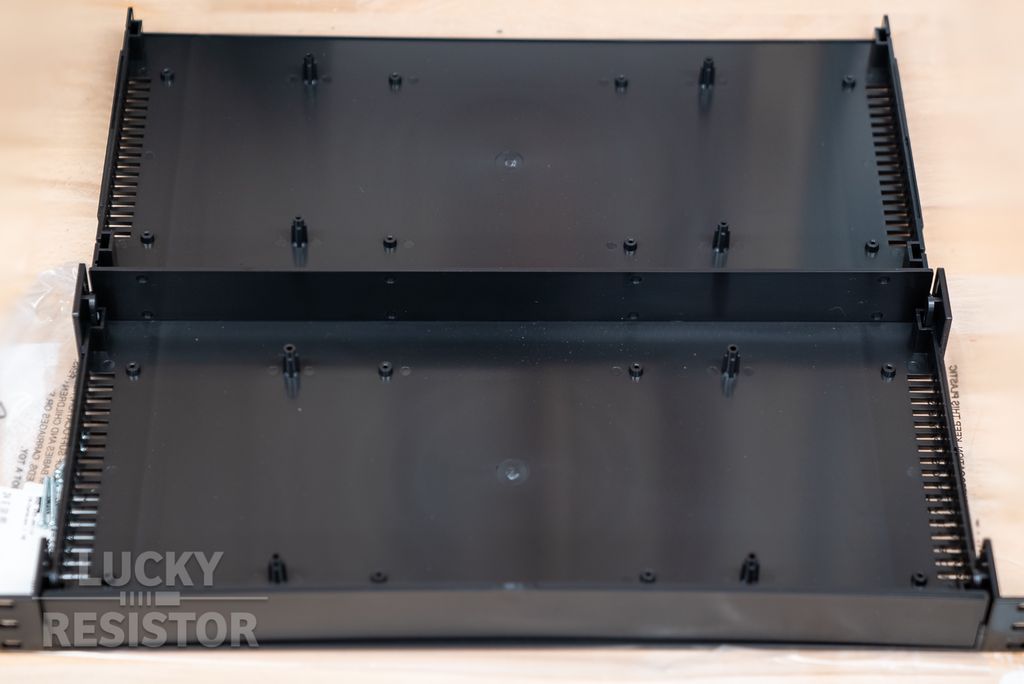
The enclosure is made from ABS and looks robust for plastic, and there are already venting slots on both sides.
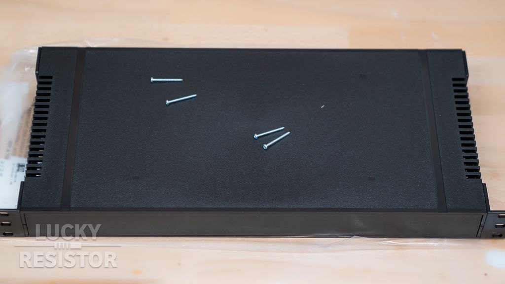
It is a smart design, with the brackets inserted into slots, so its weight is distributed along the top and bottom part of the enclosure. The top and bottom parts of the case are fastened using four screws.
This design will obviously does not work for a heavy device, but it is robust enough for the few components I will add to it.
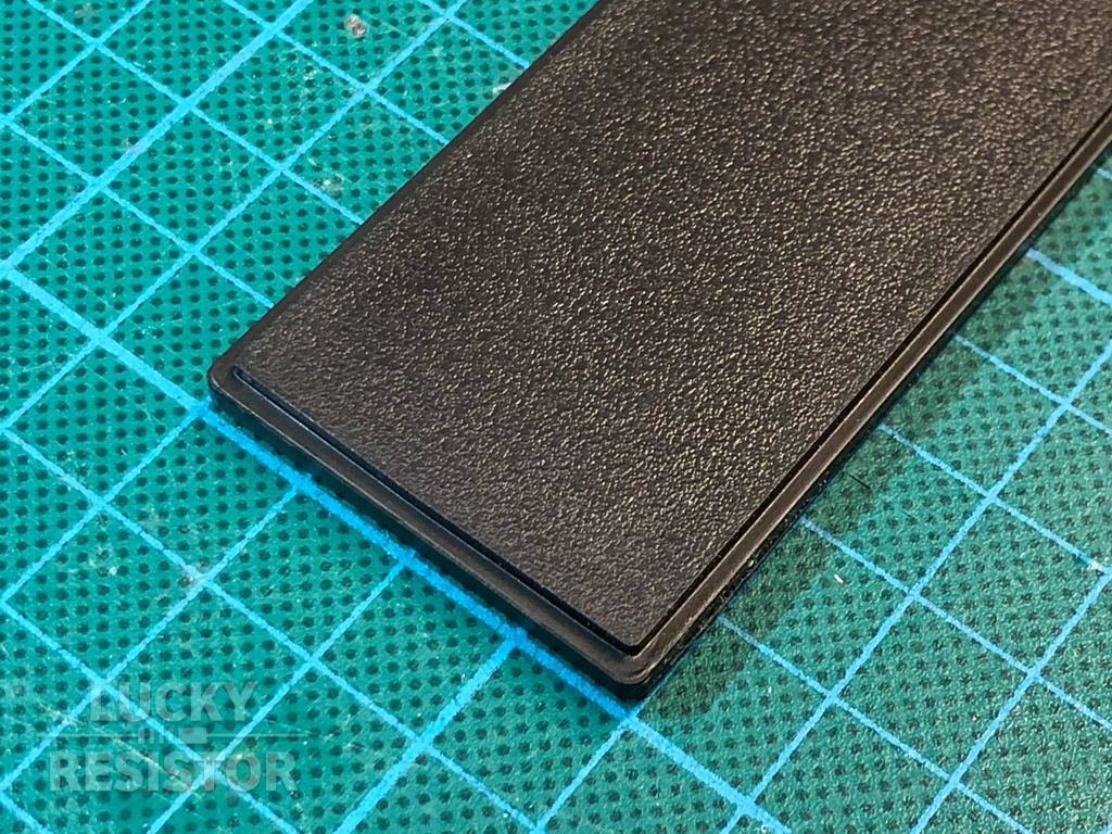
At the front and the back, there are two covers. You can easily drill holes into it, or even better, use your 3d printer to print your own covers. The covers are inserted into a slot that runs around the two shells. Therefore you can easily print many small panels and line them up in this slot. This is what I will do. 😄
Rotary Encoder for Input
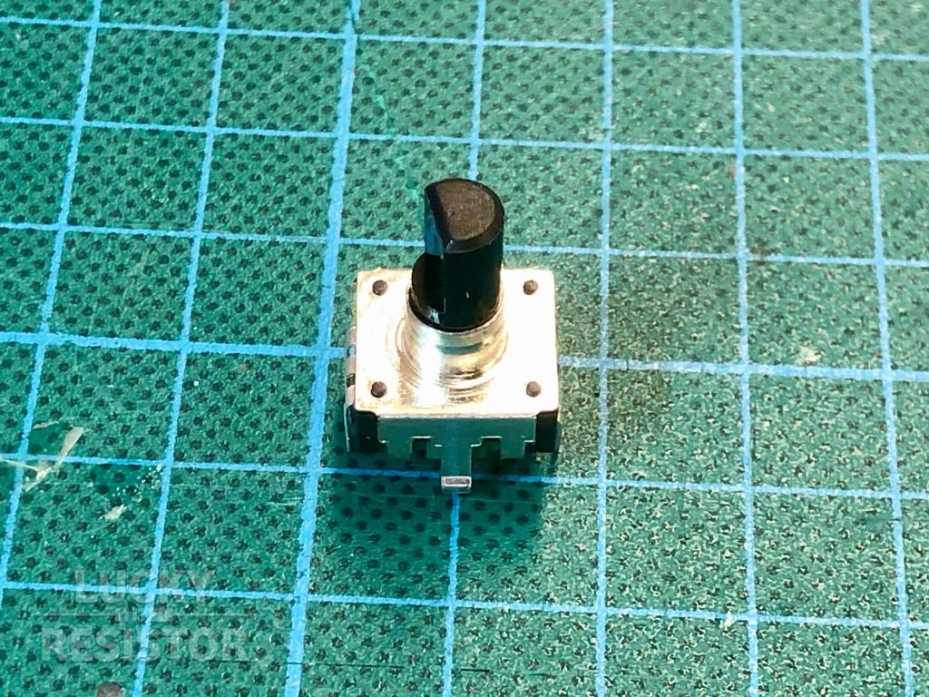
To display additional information or reconfigure the temperatures, I like to add a rotary encoder to the controller. I use one of the cheap Bourns rotary encoders:
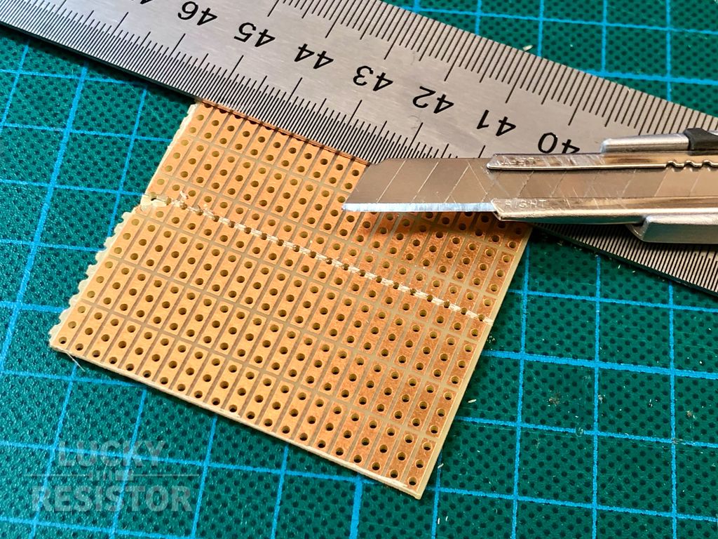
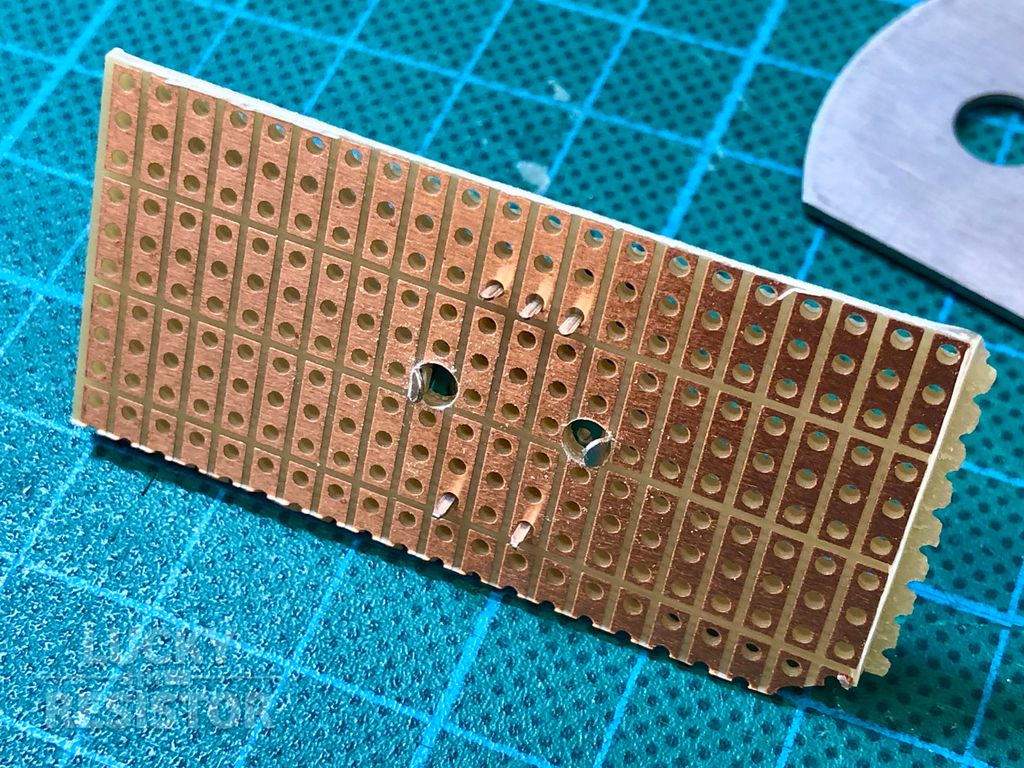
For the filters and connections, I cut a prototype board to approximate the right size.
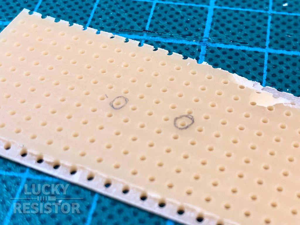
I add two 3mm holes for the fins of the encoder.
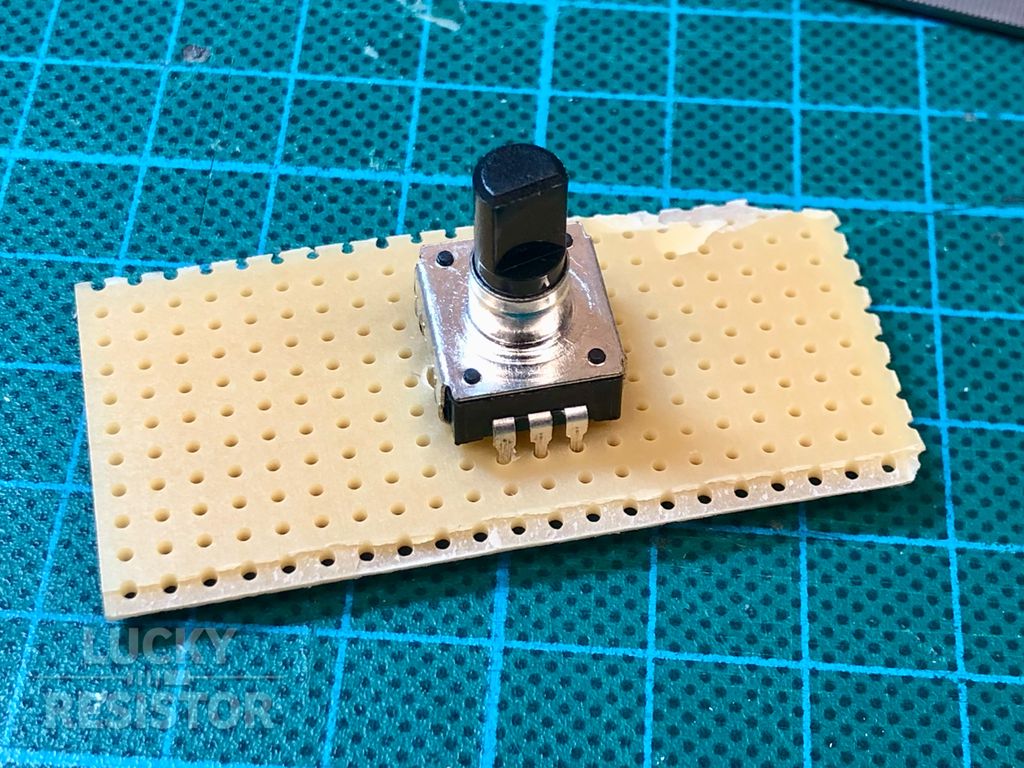
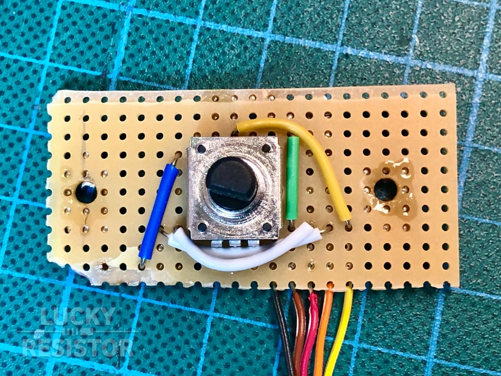
Now, the encoder sits perfectly on the board.
Adding a Filter Circuit
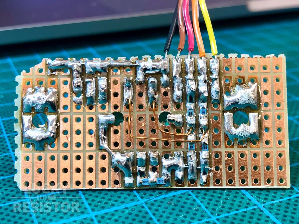
I solder a ribbon cable to this board and add three filter circuits for the switches in the rotary encoder.
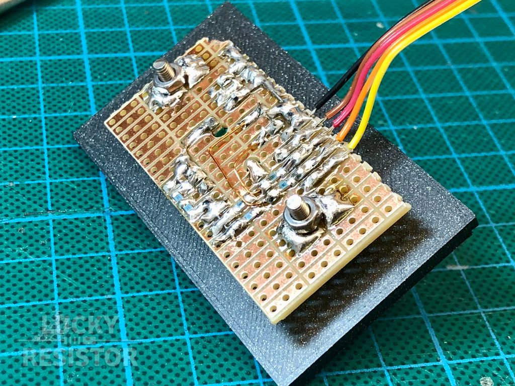
If you look closely, you can see the embedded SMD resistors and capacitors. There are no components and only some wires on the top side of the board. I added two 3.5mm holes on both sides to fasten the board to the panel. The solder blobs around these holes are there to get some distance between the screw nut and the board.
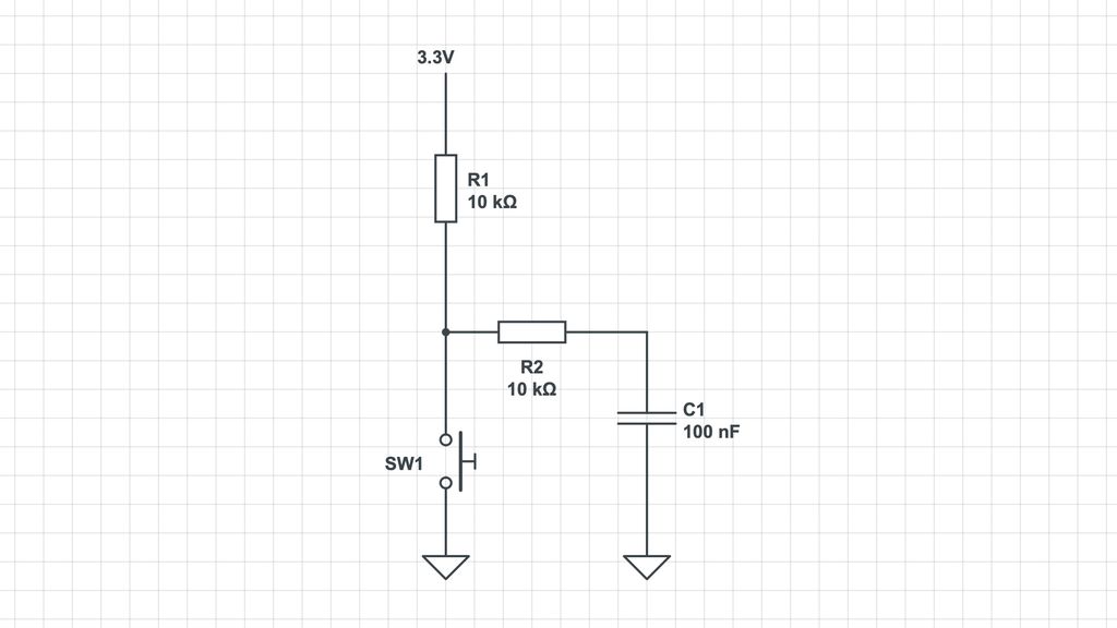
I use the filter circuit from the spec sheet with the suggested values:
Testing the Circuit
Before I continue, I do a quick test of the filters.
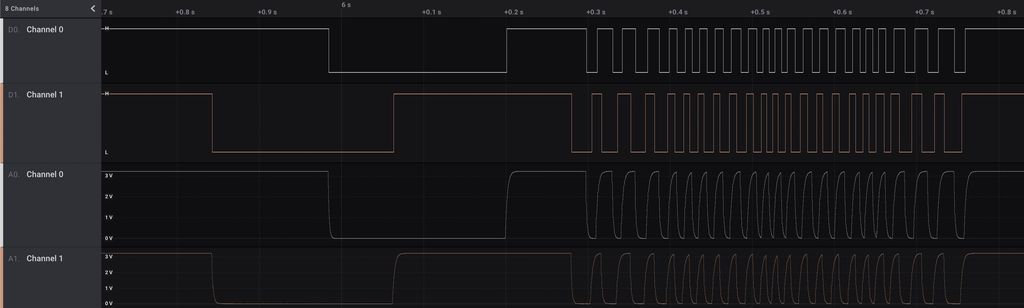
I use my Saleae logic analyser for this task, recoding the signals I get from the board while I rotate and press the rotary encoder.
On the left side, you see a slow rotation by one step, and on the right side, there is a fast rotation. The signals are perfectly clean, with no visible noise. It should be easy to use these inputs with no software filters.
Printing the Panel
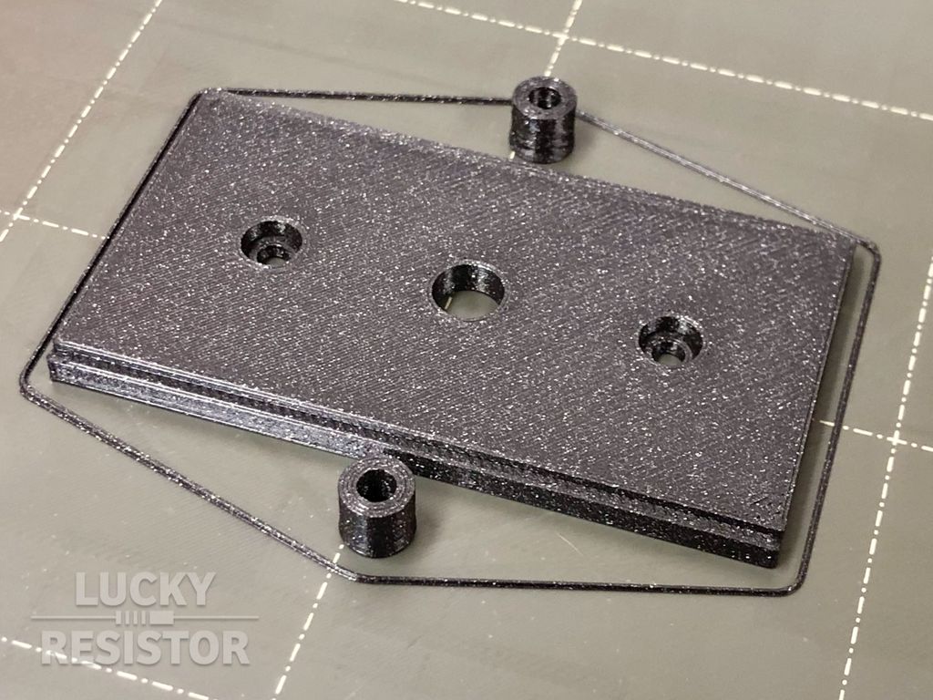
Next, I print a small section of the panel for the rotary encoder.
The panel is made for two M3 screws. I also printed two spacer to keep the right distance between the board and the panel.
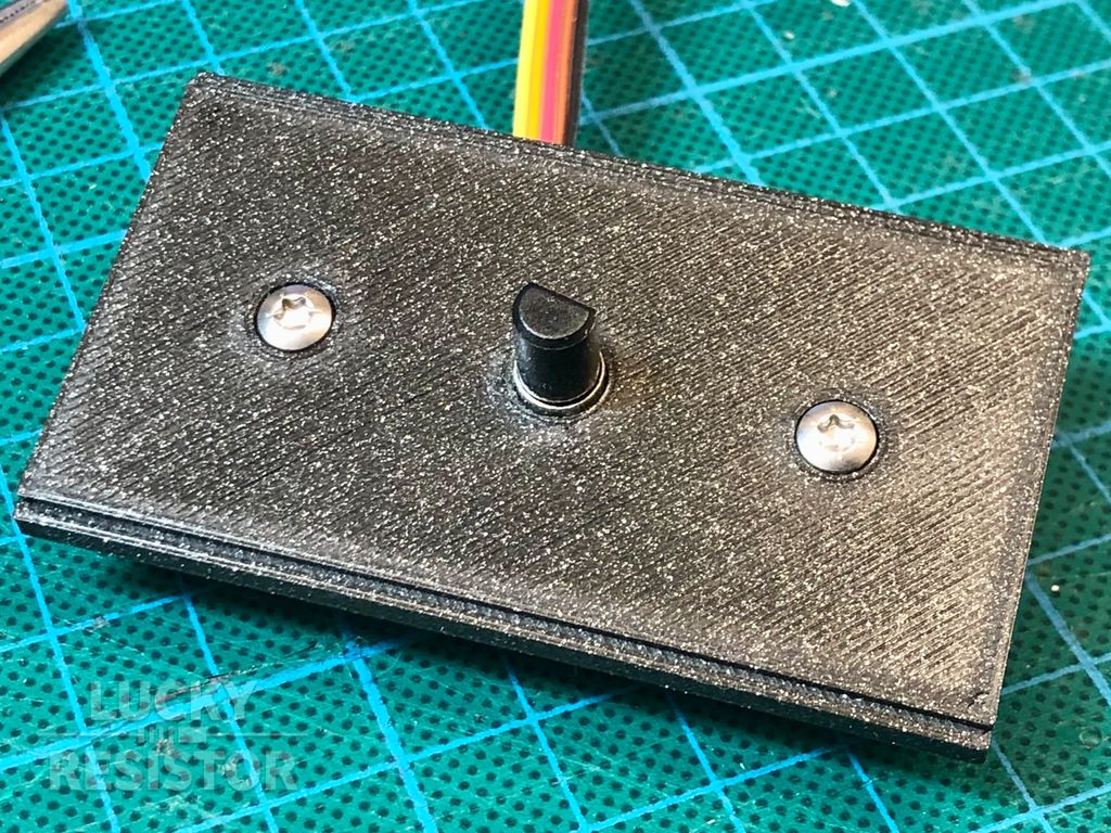
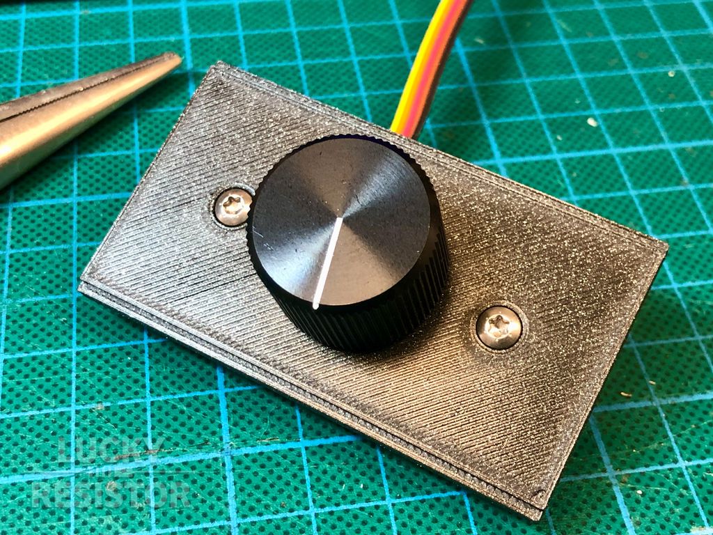
Here, I assembled the panel and the board using two M3 screws. I had to drill out the hole of the printed part to the exact diameter.
On the front, you can see the shaft of the rotary encoder. Now, I have to add a nice knob.
There is a wide range of Knobs of the RND brand from Distrelec. Some of them are looking really nice; many look outdated. If you design a device that should look like from 1970, have a look at the knob RND 210-00283. 😂
Building a Connector
Now, I build a simple connector using a one pin header.
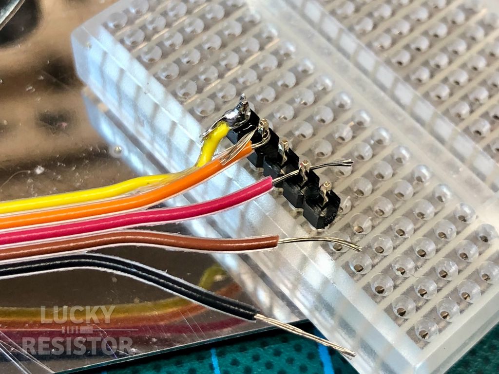
First, I stick the header into a small breadboard. I form small loops with the wires and “hook” them on the pins. That way, I can easily solder these thin wires to the header.
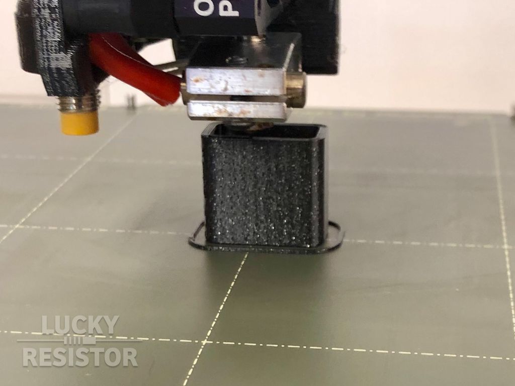
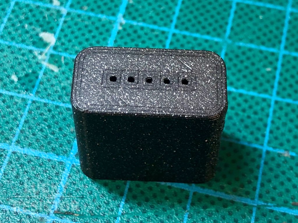
Next, I print a small enclosure for the header.
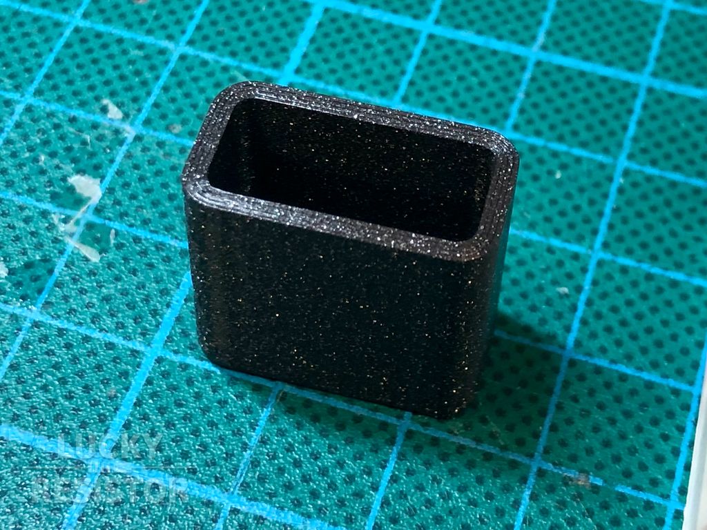
This enclosure is designed like a small cup.
It has small holes for the pins at the bottom, where the thickness is just 0.4mm.
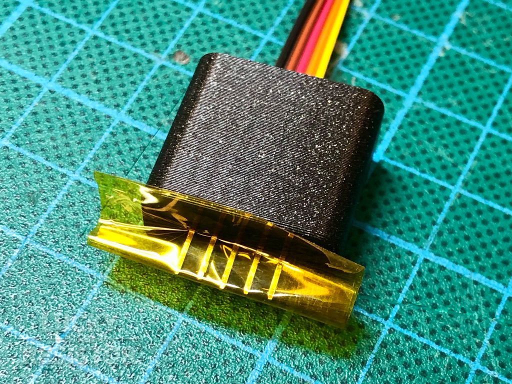
I insert the header and align the pins with the holes at the bottom. To lock the pins in place, I add some tape to the pins. This will hold the pins at the bottom of the enclosure, so they have more or less the same length at the end.
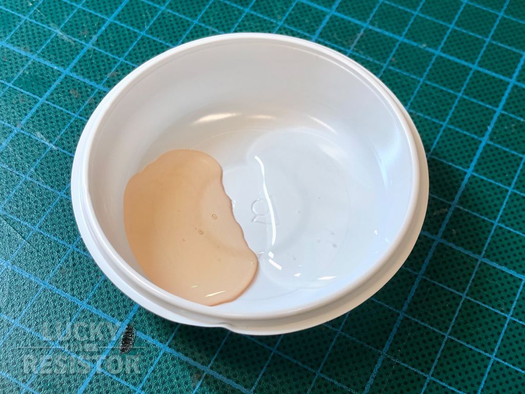
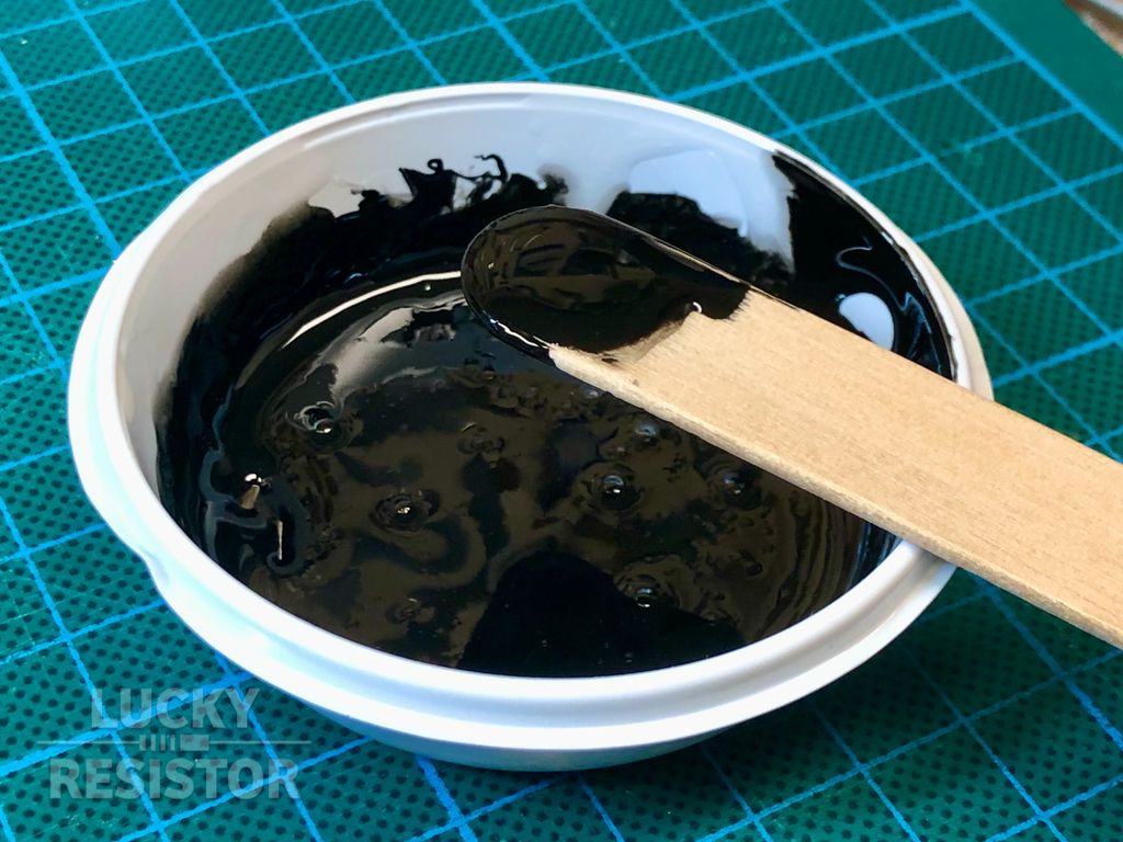
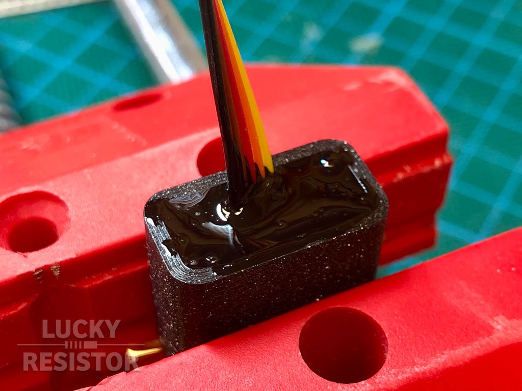
First, I put some hot glue into the enclosure, to fasten the header at the bottom and seal everything up. Next, I mix 10-minute epoxy and add black colour to it.
Now, I fill the enclosure with the epoxy and let it cure. If some of the epoxy is leaking into the tape, you can remove it with a knife, when it is almost cured.
Print the Panel Section for the Display
I use the old version of the Adafruit Monochrome 1.3" OLED display I had lying around for some time to display the current time and temperatures. It fits perfectly into this enclosure.
One problem with using this board is the location of the mounting holes. I cannot mount the display using screws from the front because the heads of the screws would touch the enclosure.
Instead of mounting it from the front, I place it deeper in the enclosure and use the holes just for alignment.
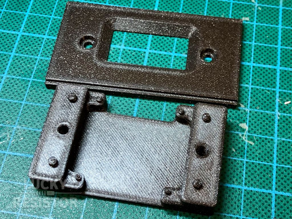
I print two parts, the front plate and a shell that sits behind it. The four inner small knobs fit into the mounting holes of the display, the larger knobs align the shell with the front plate - which has four matching holes on the back.
The large space behind the display is not just for the components on the board, I will add a small sponge in this space, which firmly presses the display to the front. This is not necessary, but prevent any rattling noises if the enclosure is moved.
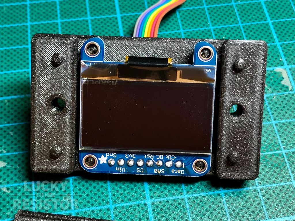
Here you can see the display in the shell, top-down. There is almost no clearance in mounting holes, but the display height is not perfectly flush with the front panel, because of the fixed layer height while printing the shell.
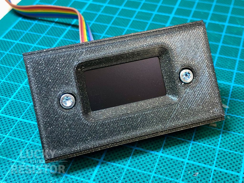
Adding the front panel fastens the display between the two parts, but puts no pressure on the glass of the OLED display.
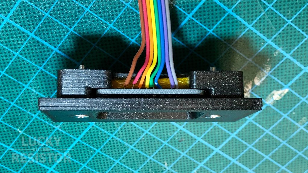
It is not well visible in the image above, but the orange thing under the ribbon cable is a small sponge, covered in Kapton tape, pressing the display flush to the front panel. The pressure is just enough to hold it securely in place.
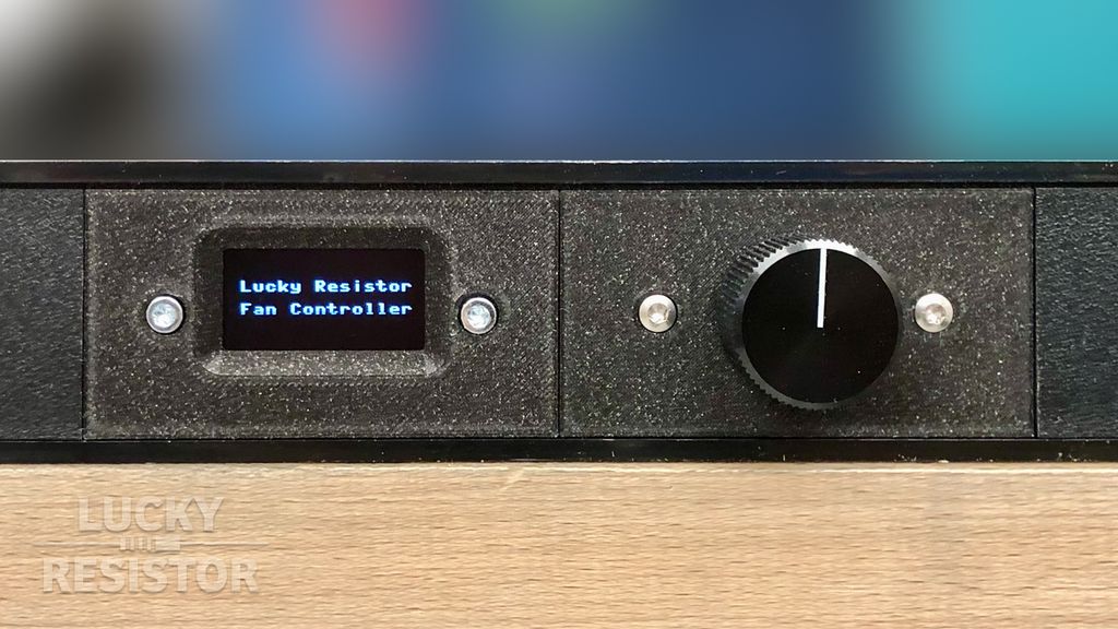
Now I cut a 140mm section from the middle of the existing front panel of the enclosure and assemble the four parts.
Hopefully, you got some inspiration from the first part of this build. Next is the back panel, where I attach the fans and temperature sensors. I had no spare fan connector sockets, so I had to order them. Therefore I will continue this build at a later time in a second part.
If you have any questions, missed information, or simply want to provide feedback, feel free to comment below or contact me on Twitter. 😄
Posted on 2018-08-31— C++, How and Why, Improve your Code
I often encounter poorly written C++ libraries, especially around hardware. In this post I outline four practical strategies—rewrite, refactor, wrap the library, or wrap the interface—to regain control, improve reliability, and reduce pain. Read on for pragmatic steps and examples you can apply to your projects.
I swapped my LM386 for an NXP TDA7052 to reduce distortion and gain more volume. The TDA7052 needs only power, an input and connects to an 8Ω speaker; I added a volume trimmer (I used 47k, 10k also works). Read the full post for the schematic and wiring details.
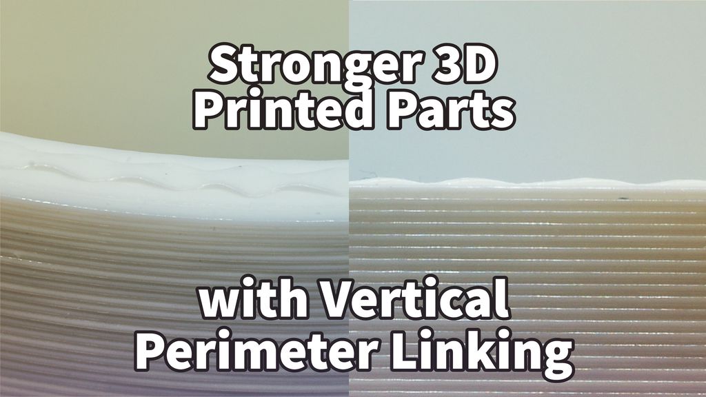
I tested a simple technique to strengthen FFF prints by adding a zig-zag vertical link between the outer and inner perimeter. My demo gcode and findings show how peaks fuse layers and slow crack propagation. If you print regularly, read the full post to see my method and limitations.
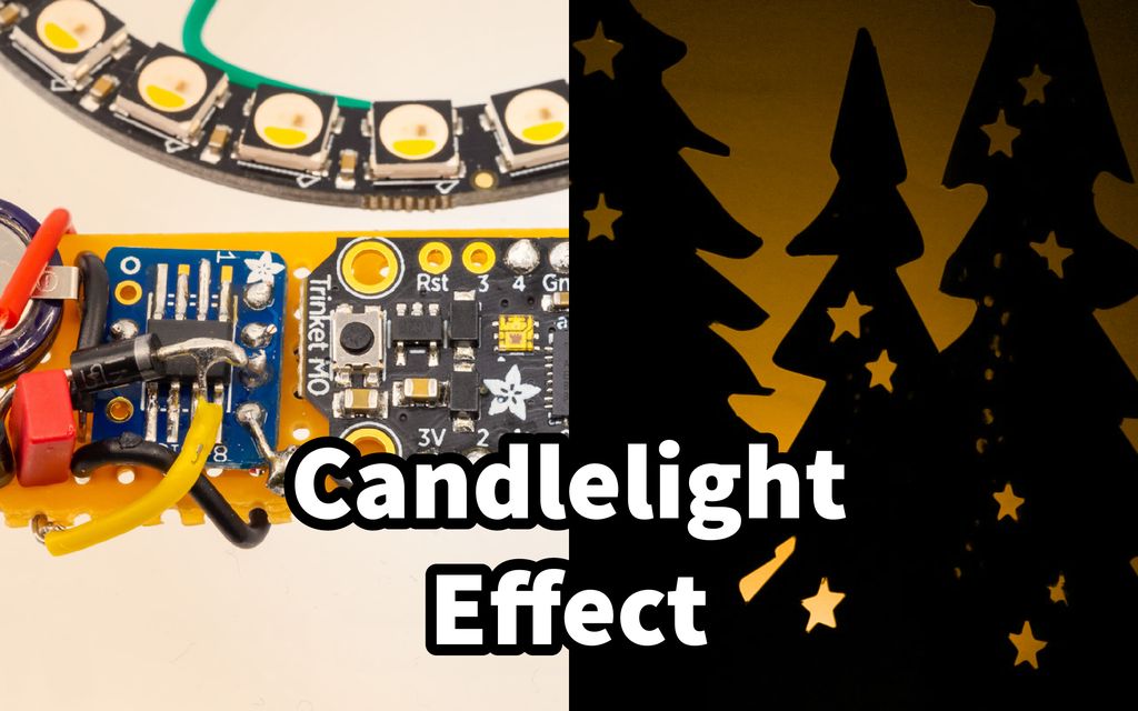
I built a compact Neopixel-based candlelight decoration with a DS3231 RTC and share the schematic, firmware, and build tips here. It's best placed behind a screen or in a jar. Read the full post for parts, assembly photos, and configuration notes to recreate it yourself.
I just received the Adafruit PCB coaster and was pleasantly surprised—photos don't do it justice. Made from 2.4mm FR4 with a transparent solder mask and black silkscreen, it blends cold and copper tones nicely. Read on for my quick impressions and close-up photos.
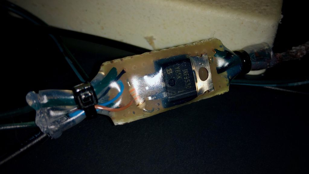
I wanted my winter decoration to switch on at dusk without constant adjustments, so I built a simple low-voltage controller using a P-channel MOSFET, a microcontroller and an ambient light sensor. I walk through my design choices, sealing for outdoor use and programming tips—read on if you'd like to build one too.