How to Create a Prototype Connector from a Pin Header
published: February 10, 2021 —
last modified: October 23, 2025
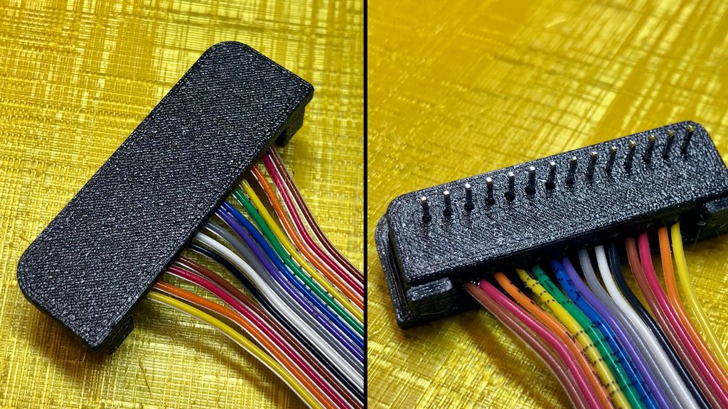
In order to test the input panel, I had to connect the 14 lines to the test setup on a breadboard. Just using a pin header was too flimsy for me, because I often reuse these test connectors on different breadboards. In this short article, I explain how I made it into a solid connector.
Table of Contents
Used Material
14-pin header
Ribbon cable
5 Minute epoxy (+colour)
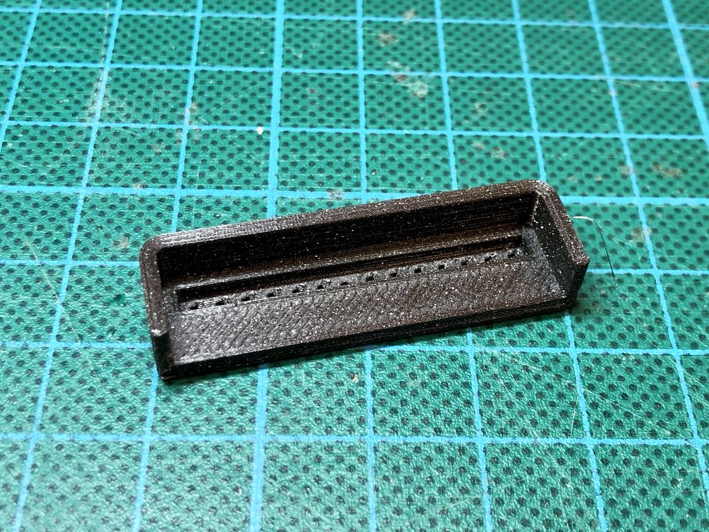
Two 3D-printed enclosure parts
Step 1: Start Printing the Enclosure Parts
Start printing the enclosure parts first so you can solder the header while the printer is running.
Have a look at my really simple design. You can download the Fusion360 and the two STL files here:
It is a parametric design, but sadly Fusion360 fails to update a sketch if you change the pin count. So if you require a different pin count, you need to recreate the second part after changing the parameter.
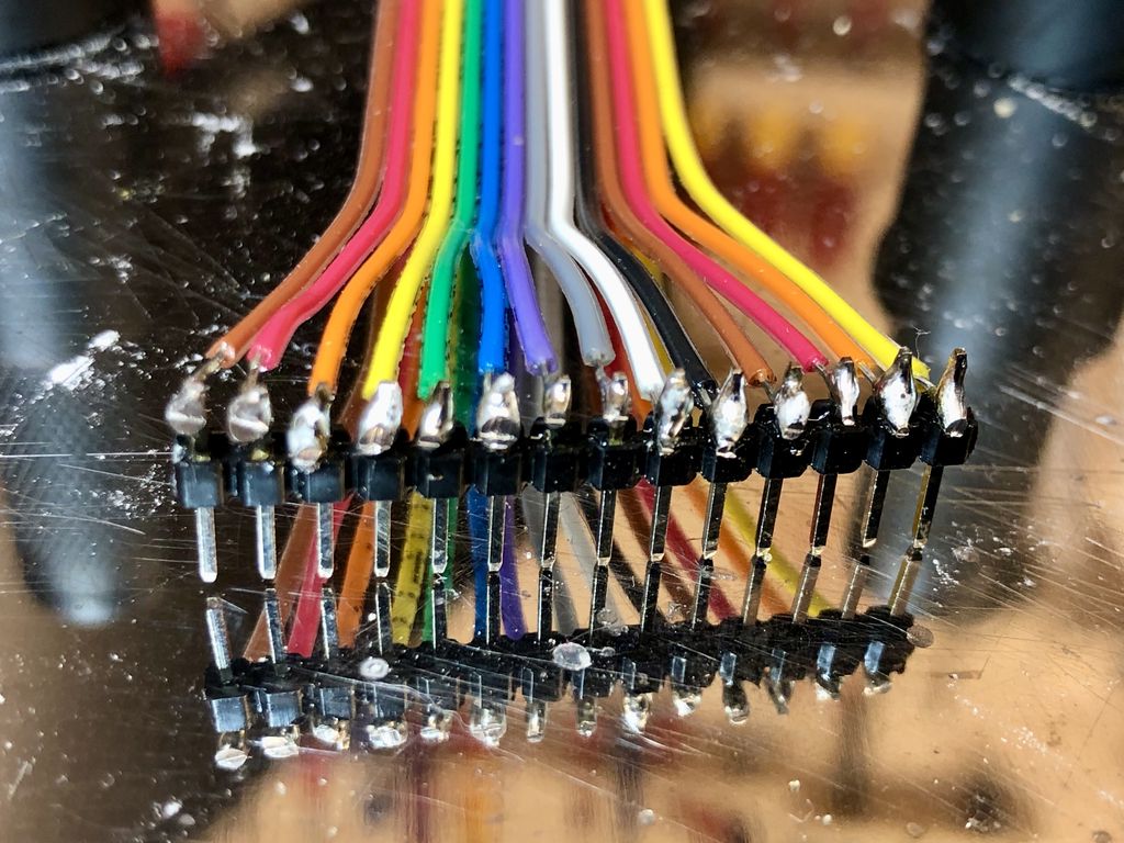
Step 2: Solder the Wires to the Header
Now solder the wires of the ribbon cable to the header. These solder joints aren’t pretty and it is difficult to solder these thin wires to the large pins.
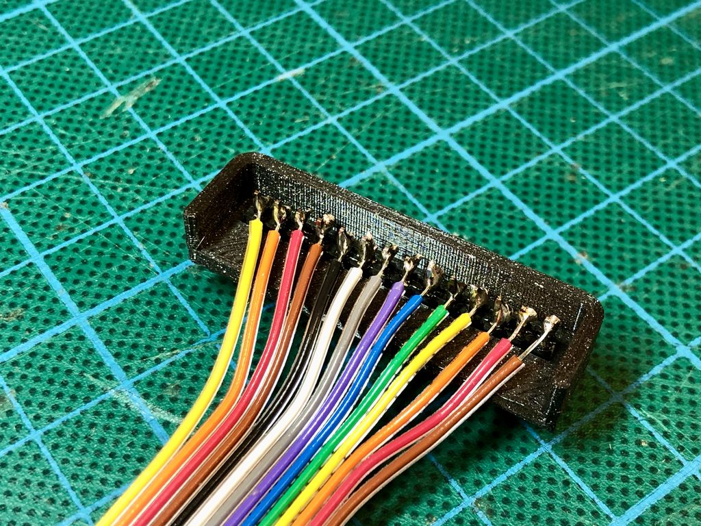
Step 3: Insert the Header into the Enclosure
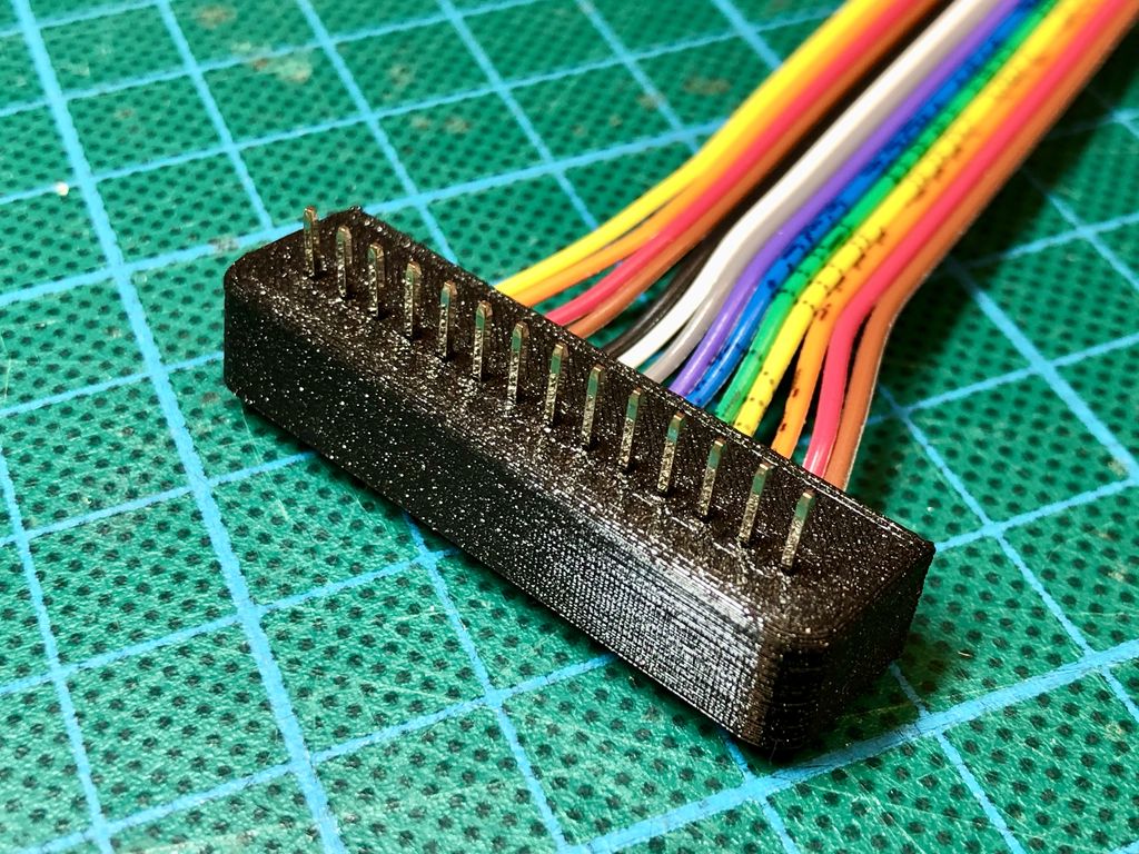
The prints should be done at this point. So inset the header into the part. It should fit perfectly into the enclosure and holds all the pins in place.
I had to adjust the pins to make sure they have the same length. This is exactly the problem I usually have by just using a header as a connector. The pins tend to slide out of the housing material.
Step 4: Fill the Part with Epoxy
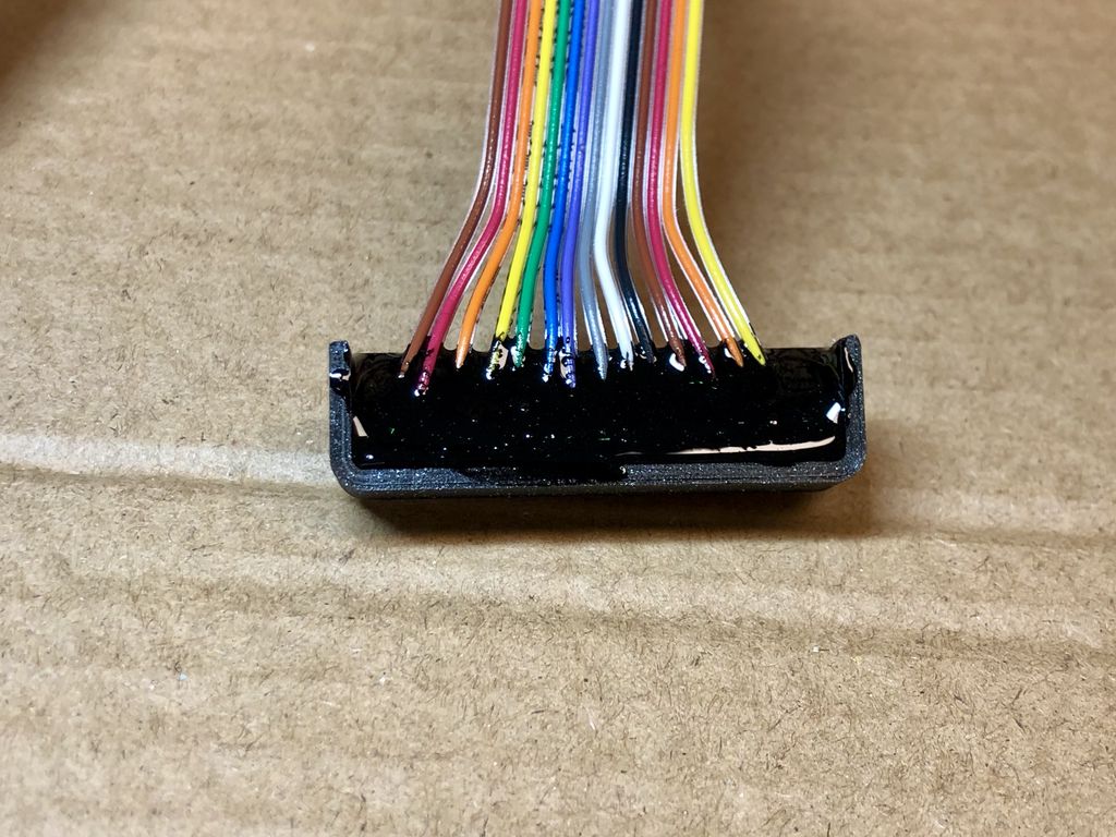
Next, fill the enclosure using 5 minute epoxy to glue the header to the printed part.
I added black colour to the epoxy and tilted the enclosure by 45º to avoid spilling.
Step 5: Glue the Lid on the Enclosure
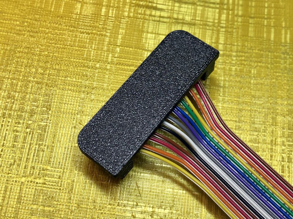
Now, use some more of the 5 minute epoxy to glue the lid on the enclosure.
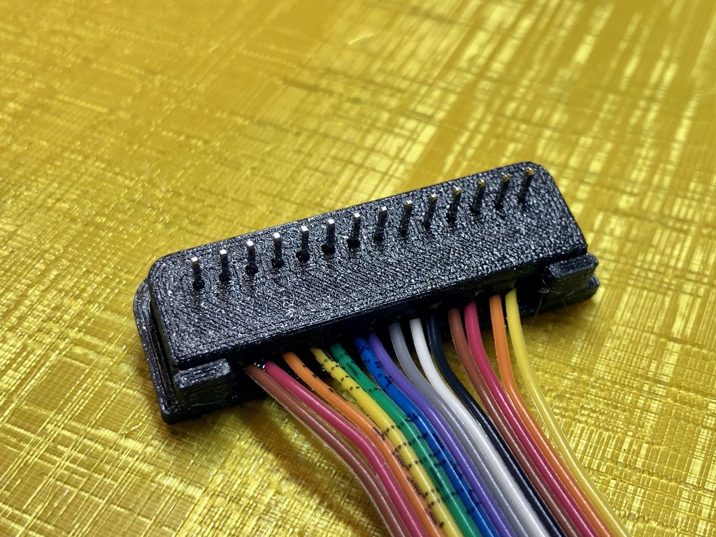
It’s a solid connector now, which can easily be inserted and removed from the breadboard. Also, you can glue a label on top of the connector as a quick reference to the different lines.
Conclusion
Creating a connector like this doesn’t take much time. If you start the print of the enclosure parts before you start soldering, the connector is ready in half an hour. Depending on the epoxy you use, it will take a few minutes longer to be fully usable.
If you have any questions, missed information, or simply want to provide feedback, feel free to comment below or contact me on Twitter. 😄
I built a simple, modular CMake-based toolchain for Adafruit Feather M0 boards that reuses Arduino tools while giving full build control. It’s aimed at prototype work and HAL development on macOS and Linux. If you’re curious, read the full post for setup steps and examples.
I photographed common SMD components through a microscope to reveal how small imperfections appear up close. I cropped each image for clarity and included a 1 mm scale and captions describing the parts. If you’re curious about what resistors, capacitors and tiny ICs look like under magnification, read on.
I built a simple, single-portion programmable cat feeder in about four days using rapid prototyping. I describe the Fusion360 sizing, plywood shell, servo mechanism, electronics, and the issues I encountered with breakout boards. If you're curious, read the full post for parts list, wiring and source code.
Posted on 2019-07-12— C++, Improve your Code, Learn
I walk through practical ways I use C++11's auto keyword to reduce repetitive declarations, simplify range-based for loops, lambdas and register access, and make Arduino and embedded code easier to refactor. Read the full post for examples and tips you can apply to your projects.
Posted on 2019-07-05— C++, Improve your Code, Learn
I walk through a practical, minimal event-based approach to firmware using Arduino examples. Step by step I refactor blink sketches into modular events, introduce a millisecond timer, prevent skipped events, and encapsulate logic into classes and modules. Read on to follow the examples and apply them to your projects.
In part three I assemble and test the prototype PCB, set ATtiny13A fuses, and refine user interaction and firmware plans. I cover LED display choices, power measurements and a modular firmware approach. If you’re building a low-cost plant sensor, read the full post for practical steps and diagrams.