published: January 30, 2021 —
last modified: October 23, 2025
In the fifth part of this series, we print the turntable and talk about the back panel of the enclosure. If you missed one of the previous parts, visit the overview page to access them.
Table of Contents
The Files
You will find all required files for the prints in the GitHub repository:
Before we start printing the turntable, let me explain some of the features of it, so you understand how they are used.
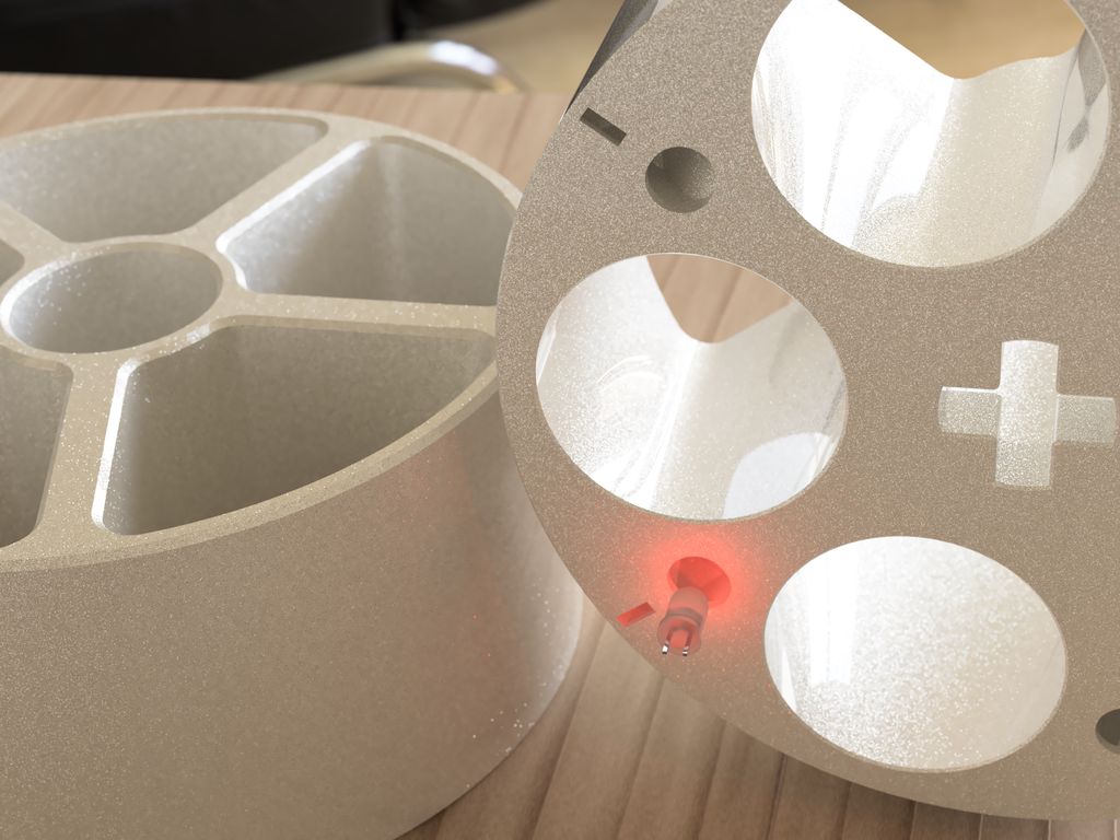
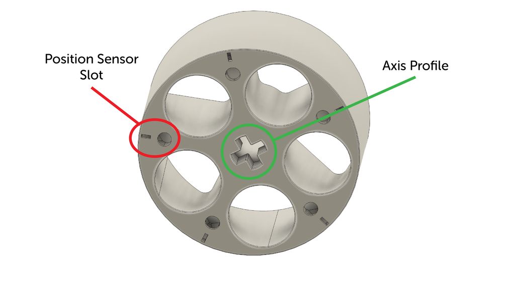
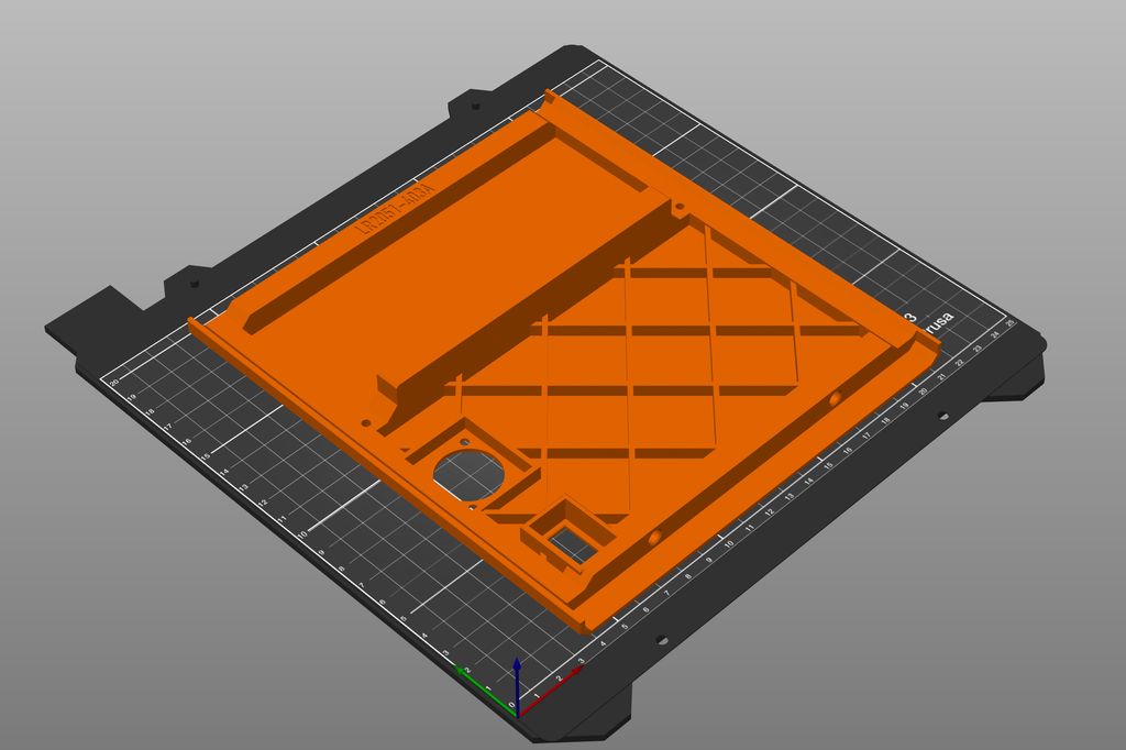
If you look at the bottom of the part, you can see the axis profile in the middle. It will interlock with the axis and drive the turntable. At the edge are five position sensor slots.
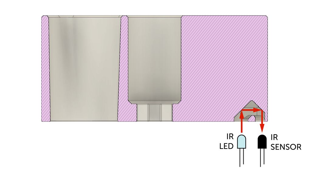
The cavity behind the position sensor slots is designed to reflect light from the larger hole back to the thin slot. If you point an IR LED to the round hole, you will get a relatively precise signal using an IR transistor placed below the slot.
This will only work if you are using a filament colour which reflects the IR wavelengths you are using for sensing. Alternatively, you can try to place aluminium foil at the top of the cavity, or just use white or reflective paint.
Also, the filament has to block the light around the slot for a precise measurement. Depending on the filament you use, you may need to paint the region black around the slot.
If you use white filament as suggested, it should work with no additional paint or foil. Depending on how you like to implement the position sensor, it makes sense you cut the position slot form the model and print it for some filament colour tests.
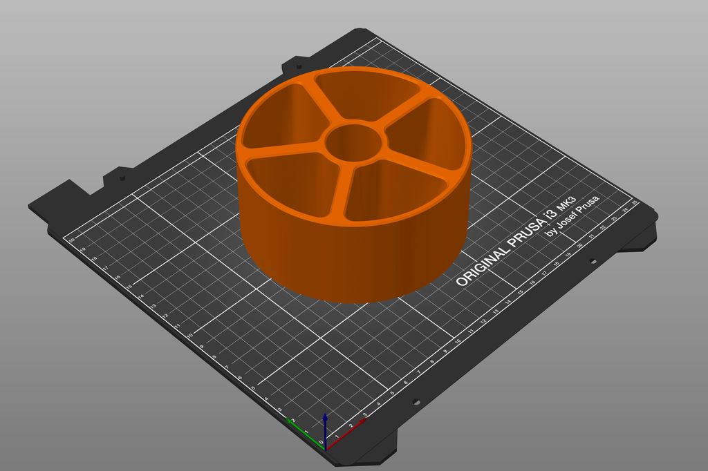
Print the Turntable
File: LR2051-501.stl
Material: PETG (Signal White)
Layer height: 0.2 mm
Print bed: Powder coated
Supports: No supports required
Difficulty: Medium
Filament: ~145g
Print Duration: ~13h
Notes: Make sure there is no warping!
About the Back Panel
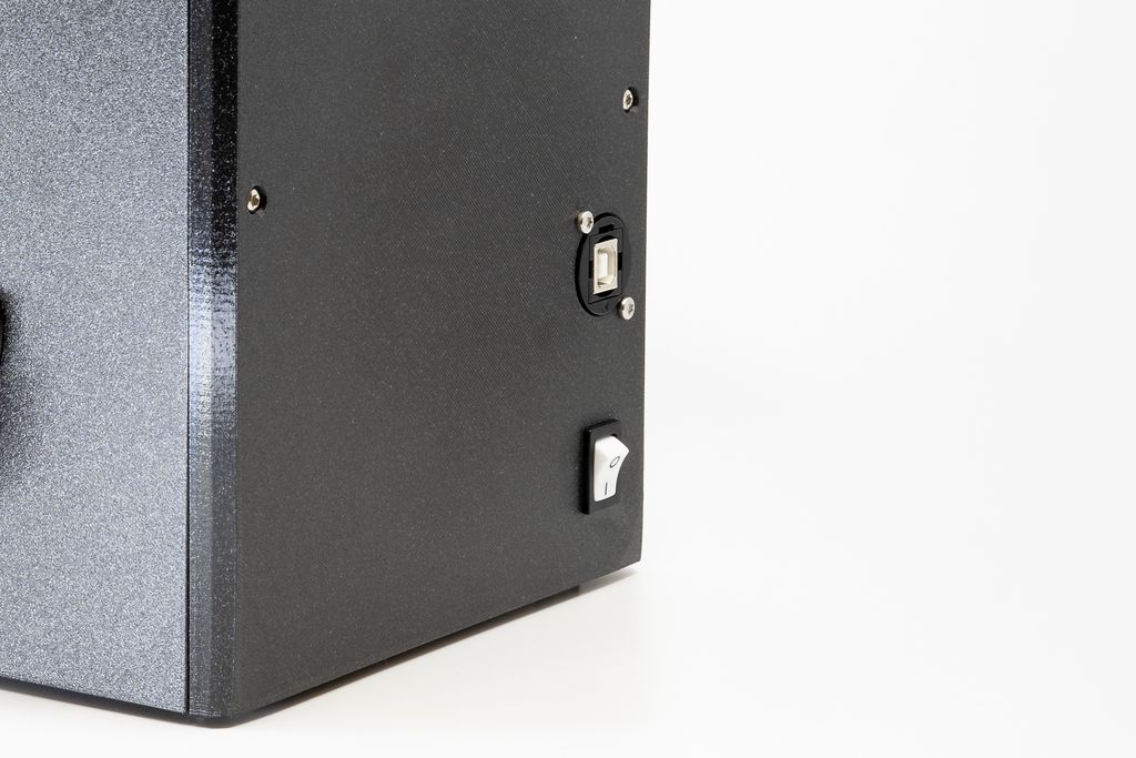
In my version of the back panel, there are two slots. The first one is for an XLR USB feedthrough adapter and the second one for a large on/off switch.
The Parts I Used
The parts in the image above are:
Cliff CP30207NX USB 2.0 B to USB 2.0 A feedthrough adapter I like this adapter from Cliff, because they look very neat on the outside and you can replace them with another interface. Meanwhile, there is also a white version of this adapter. You find also USB-C adapters, but sadly no micro-USB ones.
C&K DA102J11S215PQF Switch There are many variations of this switch, with different colours and symbols. These switches are not cheap, but they are nice to look at and flip with a satisfying click.
How to Customize the Back Panel
If you like to use other components, you have several options to customise the back panel.
Along with the STL files, you also find a Fusion360 design LR2051-403A.f3d. If you are experienced using Fusion360, you can simply remove my features and add your own to the design.
If you are used to modify mesh files directly, I provide the file LR2051-403A-E.stl, which has no slots. You can use this mesh and add the required openings for the components you like to use.
In case you run into problems, or have any questions, please use the comments below or reply to the post on Twitter.
Print the Back Panel
File: LR2051-403A.stl or your custom design. or your custom design.
Material: PETG (Galaxy Black)
Layer height: 0.2 mm
Print bed: Powder coated
Supports: No supports required
Difficulty: Easy
Filament: ~138g
Print Duration: ~10h
Insert the Insets
After printing the front and back panel, we have to insert the insets into these parts. This time, I won’t provide illustrations of the exact locations, because you may have printed a custom design.
Just look for the inset holes you found on all the previous parts. The front and back panel are fastened with screws from the base plate and the top plate. The back panel also provides a support for the rotary table and is fastened to the left and right panels using two additional screws.
Conclusion
Mechanically, these were the last parts to be printed (except a knob for the rotary encoder). If you like, assemble the whole device and run some tests. If you drive the stepper motor, the rotary table should rotate easily on top of the platform and dispense dry food you put into the compartments. 🎉
In the next part, we will talk about the first electronic board, the input panel. It is quite simple, just a place for the rotary encoder and four LEDs.
If you have any questions, missed information, or simply want to provide feedback, feel free to comment below or contact me on Twitter. 😄
I created a small macOS app that converts bitmap 8×8 fonts into byte arrays for text-only LCD displays. It accepts PNGs, validates the layout, and outputs source code you can save or copy. I also provide an example font, a Photoshop template, and the source—read on for download and usage.
I designed a set of 3D-printable round corner templates specifically for woodworking and routing. They’re optimized for 0.4mm nozzles and 0.2mm layers, include snap-in guides, screw holes, and metric/imperial sizes. If you often rout rounded edges, read the full post for printing tips and mounting options.
I guide you through writing a near-final firmware for my cheap plant watering sensor, describing module structure, incremental development, and practical tests. I cover ADC sampling, oscillator checks, EEPROM settings and a prototype fix for the push-button. If you’re building a similar device, I invite you to read the full post.
I added a stable Hitachi LCD driver to the HAL layer, using an MCP23008 backend to cut wiring and simplify hardware. This post walks through parts, firmware repositories, and how to run the demo via serial shell. Read the full article for setup steps, code links, and usage tips.
I guide you through building a compact particle sensor node using a Raspberry Pi Zero W and a minimal custom shield, with published Gerbers, STL files and example code. I keep the design simple and extendable—if you'd like to build your own networked air-quality node, read the full post for parts, assembly and setup.
I walk you through using the RP2040's PIO to measure a PC fan's RPM with a small software filter to ignore short spikes and timeouts. I explain the PIO routine and a simple RpmInput wrapper in MicroPython—read on if you'd like the code and practical setup tips.