One long M3 screw, 40mm or longer to insert the insets.
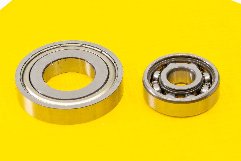
2 × ball bearing 6200 10×30×9 mm
2 × ball bearing 16004 20×42×8 mm
NEMA 17 stepper motor with 5mm diameter D-shaft (almost any variant will work).
One or more rubber bands.
The Insets
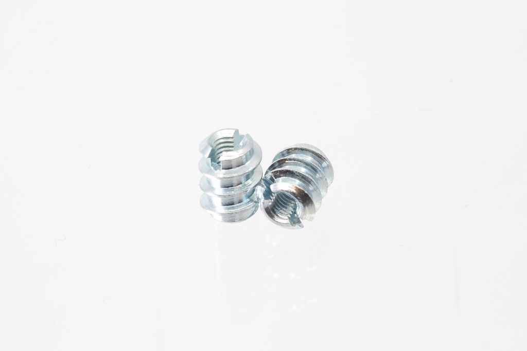
I use insets from Rampa for this build. They are made of steel, not too expensive and align very well in the prepared holes. If you use a differente type of inset, make sure it is no longer than 8mm.
The Ball Bearings
Because the whole gearbox is made of plastic, these bearings are just used to eliminate any friction. Therefore you can use really cheap bearings, as long they spin freely.
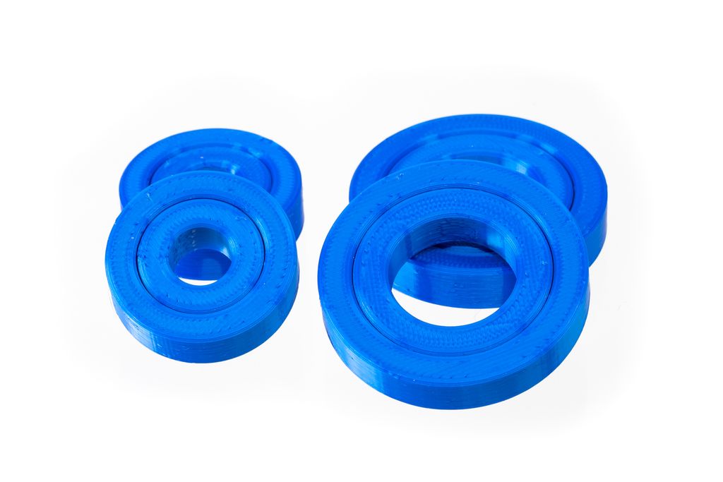
Alternatively, for testing, you can print the bearing mockups.
After printing these, use lubricant paste or spray, suitable for the used plastic to reduce friction. This is no permanent solution, but it will work for the first tests.
How to Insert the Insets
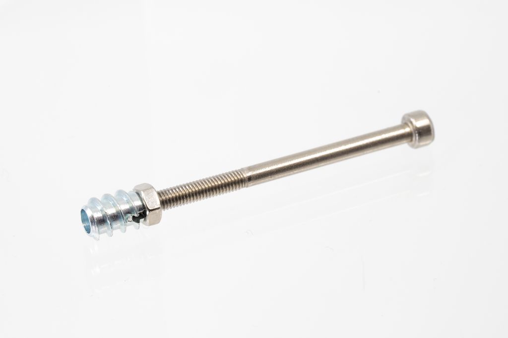
Do not simply screw the insets into the prepared holes of the objects, it will create cracks. First prepare a long M3 screw like this:
The screw enters 2-3 mm of the inset and the nut is barely tightened.
Procedure
Use a lighter to heat the inset for 4-6 seconds. Now, you have to work quickly.
Position the hot inset in the hole and lightly screw it in by hand.
Check the correct alignment of the screw.
Use the screwdriver to screw the inset into the hole, until the nut touches the side of the object.
Immediately start unscrewing it. The inset should stay in the hole.
Watch the following video to see all these steps:
If the inset does not stay in the hole and unscrew itself, wait until it is cooled. Now unscrew the inset until you can grab it with pliers. Hold it in place while you unscrew the M3 screw from the inset. Now use a screwdriver to screw the inset back into the object.
Assembly
Insert all Insets
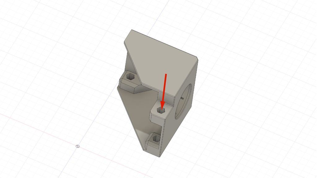
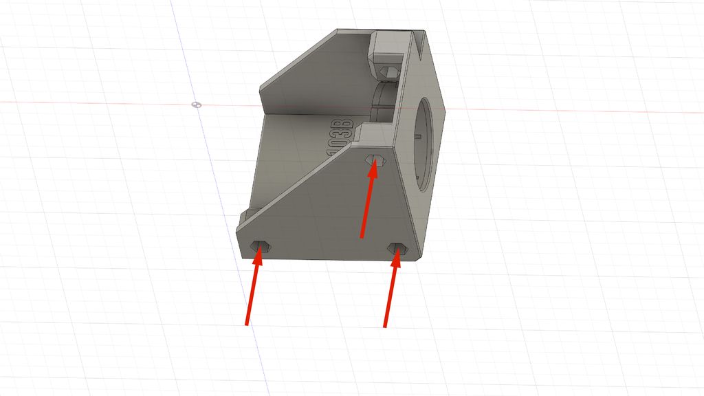
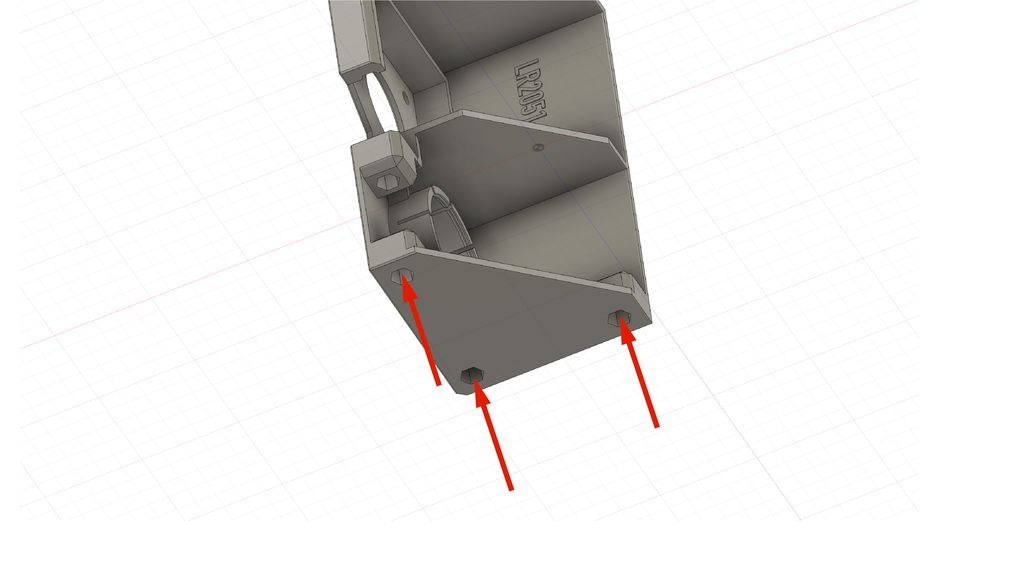
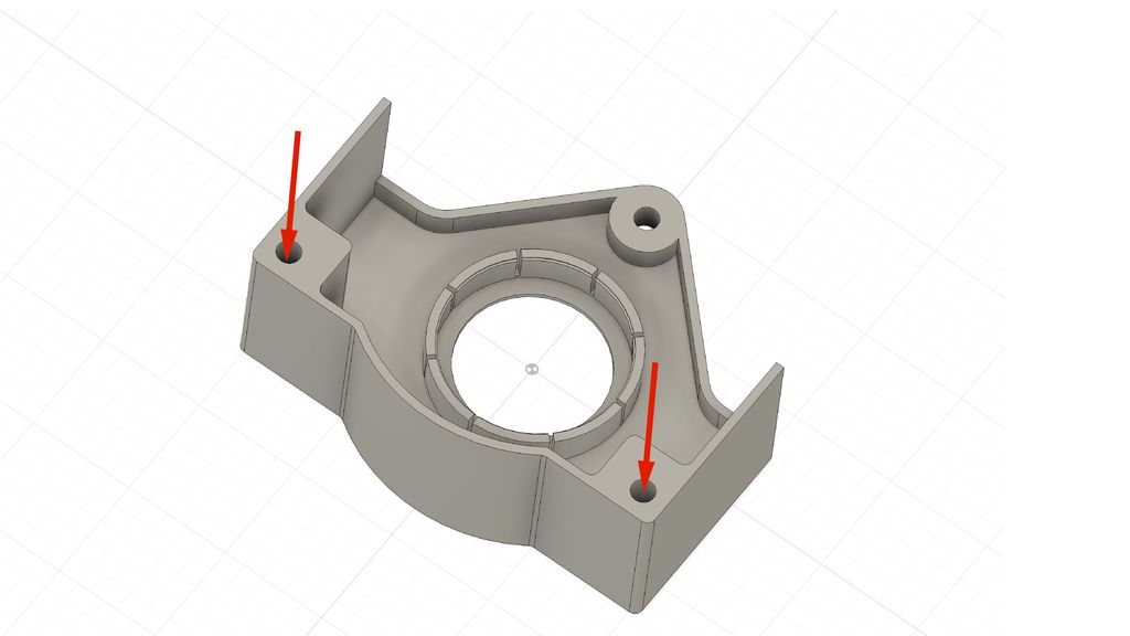
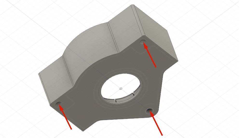
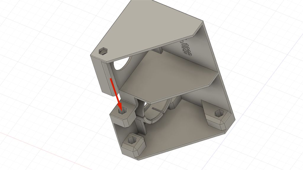
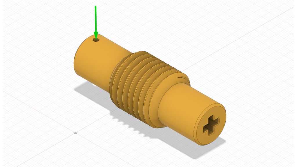
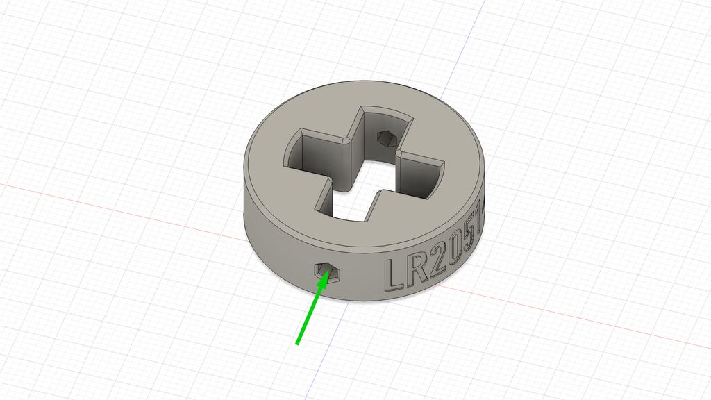
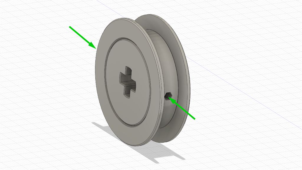
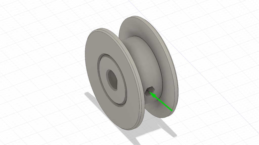
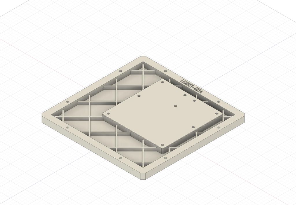
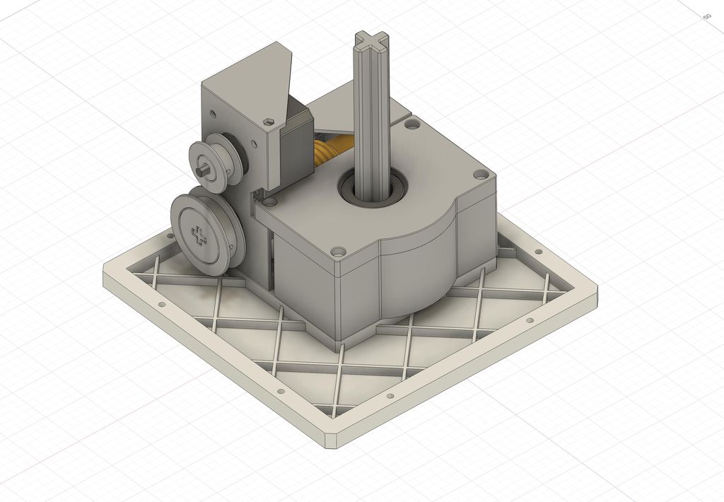
Start the assembly by inserting all insets into the printed objects. See the following images for all locations.
Most of them are straightforward as shown, except the last one. Here you have to use a short M3 screw, hold the inset using pliers to heat and place at the right location - then use a screwdriver from above trough the hole in the part.
Insert the Grub Screws
Next, insert all the grub screws into the parts. For the worm screw and the two spacers, just screw it into the part, until it is flush with the inner wall.
The first wheel requires two grub screws. Assemble the two wheel parts and screw the first one in, until it is flush with the inner wall of the part. In the opposite hole, screw the grub screw in, until it is flush with the outer wall. This second one will hold the two parts together.
Assemble the second wheel and screw the grub screw in until it is flush with the inner wall. It should keep the two parts together. In doubt, use a second screw in the way we used it for the first wheel.
Assemble all Parts
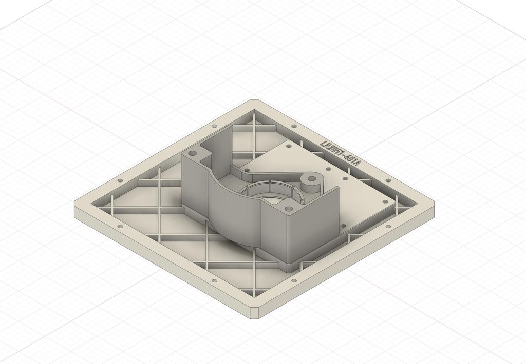
Start with the base plate.
Use three 8mm screws to fasten part LR2051-101B to the base plate. For all following parts, keep the screws loose first and fasten them at the very end.
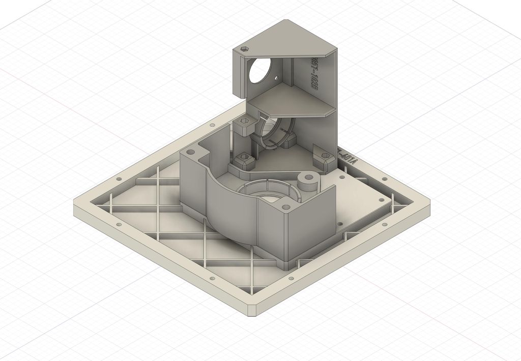
Fasten part LR2051-102B to the base plate.
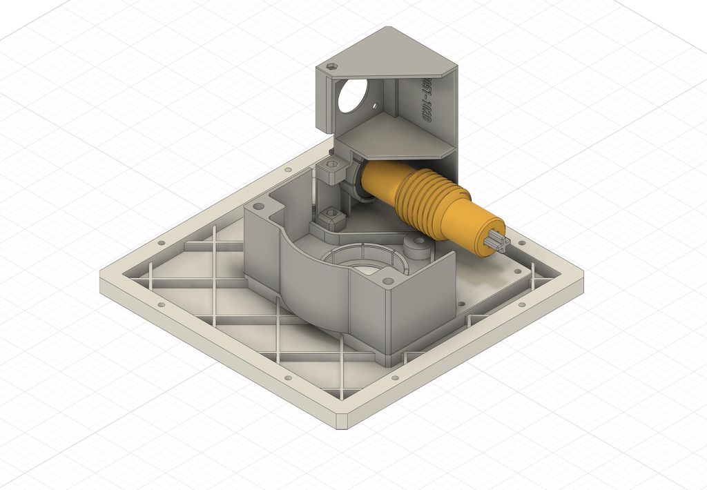
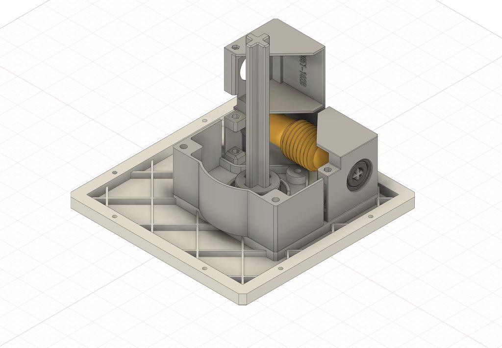
Now insert the bearing in part LR2051-102B and assemble the worm screw LR2051-111B and the axis LR2051-108B. Do not fasten the grub screw yet. Insert the axis into the bearing.
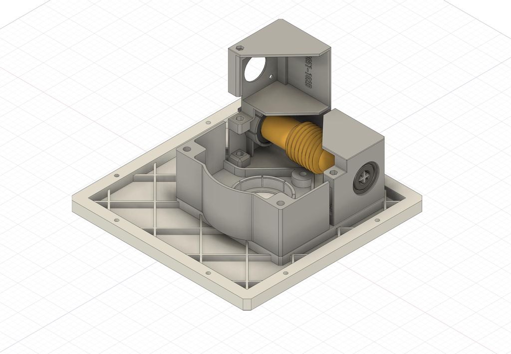
Now insert the bearing in part LR2051-103B, insert the axis and fasten the part to the base plate.
Next, make sure the axis is flush with the bearing at this side and fasten the grub screw.
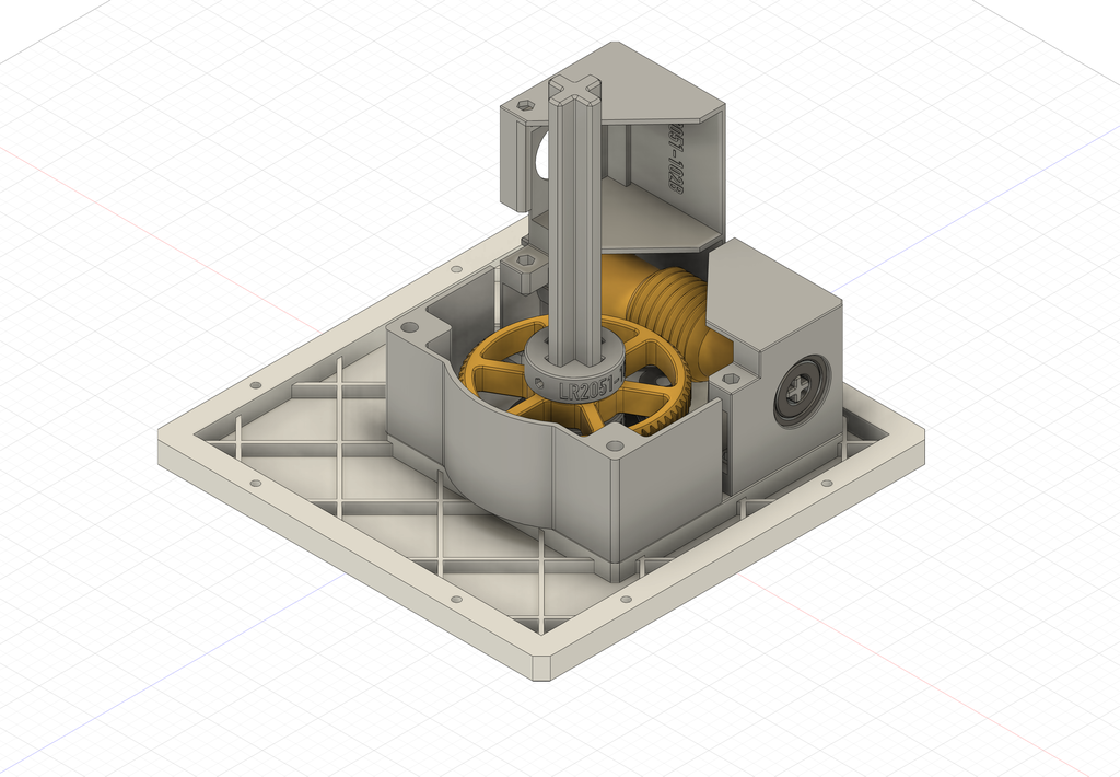
Insert the bearing in part LR2051-101B. Assemble axis LR2051-107B with the spacer LR2051-105B and insert it into the bearing. Make sure the axis does not touch the base plate. Now fasten the grub screw on the spacer.
Add the gear wheel LR2051-112B to the axis and put the second spacer on top. Fasten the grub screw on this second spacer flush to the gear wheel.
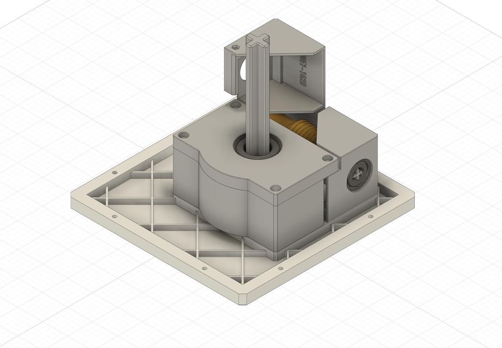
Now insert the bearing in part LR2051-104B and put it on top of the assembly. Insert screws in all four holes and fasten the part to the other parts.
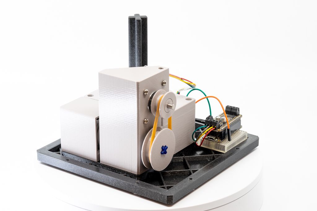
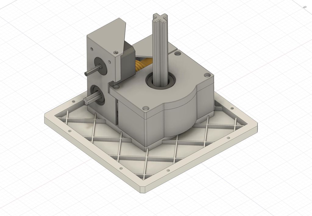
Next, insert the NEMA stepper motor and fasten it to the gearbox using three short m3 screws.
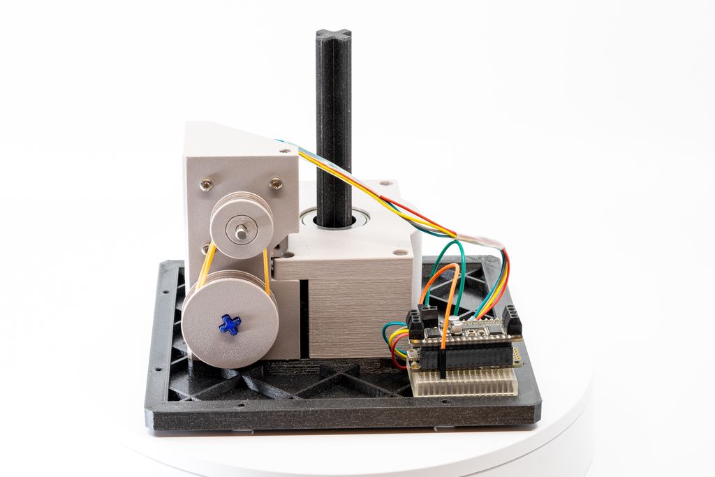
Now put the two wheels to the motor and worm wheel axes. Make sure they are vertically flush and they run freely. Add one or more rubber bands to connect the two wheels.
Everything should run freely, with almost no force. If this isn’t the case, make sure there is no warping.
Test the Gearbox
Use a controller and stepper motor driver of your liking to test the gear box. Everything should run smoothly and the rubber band should be enough to drive the worm gear.
The axis for the turntable does not have to rotate fast, one rotation every 20 seconds is already enough for dispense one compartment in four seconds.
Conclusion
This is the end of the second part. In the next part of this series, we will print the enclosure panels and the turntable platform. These will be very time-consuming prints.
If you have any questions, missed information, or simply want to provide feedback, feel free to comment below or contact me on Twitter. 😄
I've been developing software for over 20 years and share how my language preferences shifted—from assembler and C to Python, Swift, C++, Go and Rust. I outline use-cases and trade-offs in a personal, practical way; if you're deciding what to learn, please read the full post for detailed guidance.
I've released Lucky World, a compact jump'n'run for the MeggyJr RGB featuring an intro, 16+ levels, secrets and an end scene. I squeezed it into ATmega328P limits and shared the sources under GPLv2. If you're curious, please read on for downloads, requirements, and play instructions.
In part three I assemble and test the prototype PCB, set ATtiny13A fuses, and refine user interaction and firmware plans. I cover LED display choices, power measurements and a modular firmware approach. If you’re building a low-cost plant sensor, read the full post for practical steps and diagrams.
I designed a modular 19th‑century‑style lantern you can 3D print as a candlelight or expand into an LED street‑lamp stand. Read on for my glue‑free assembly, colour‑layer printing tips, and stand options — or jump to the Printables page for downloads and print instructions.
I guide you through building a compact particle sensor node using a Raspberry Pi Zero W and a minimal custom shield, with published Gerbers, STL files and example code. I keep the design simple and extendable—if you'd like to build your own networked air-quality node, read the full post for parts, assembly and setup.
I walk you through using the RP2040's PIO to measure a PC fan's RPM with a small software filter to ignore short spikes and timeouts. I explain the PIO routine and a simple RpmInput wrapper in MicroPython—read on if you'd like the code and practical setup tips.