published: January 2, 2021 —
last modified: October 23, 2025
Do you own a 3D printer and would like to start a complex and challenging project? Then let’s print a fully functional, programmable cat or pet feeding device! 😄
In this multi-part series, I will guide you step by step through the printing and assembly process of all mechanical parts. I will also provide PCB layouts and examples for the required electronics, except for the controller. Here, the range of suitable controllers is too large to restrict you to a single solution.
I will provide all required files for free under an open source license.
Table of Contents
About the Device
If you follow my blog, you may remember the original prototype of the cat feeder from 2017. After a few months in use, I started to develop an improved version of the device.
I went through several iterations using different technologies, but finally - as a result of the pandemic - the 3D printed version was the only feasible one. 😄
Composition
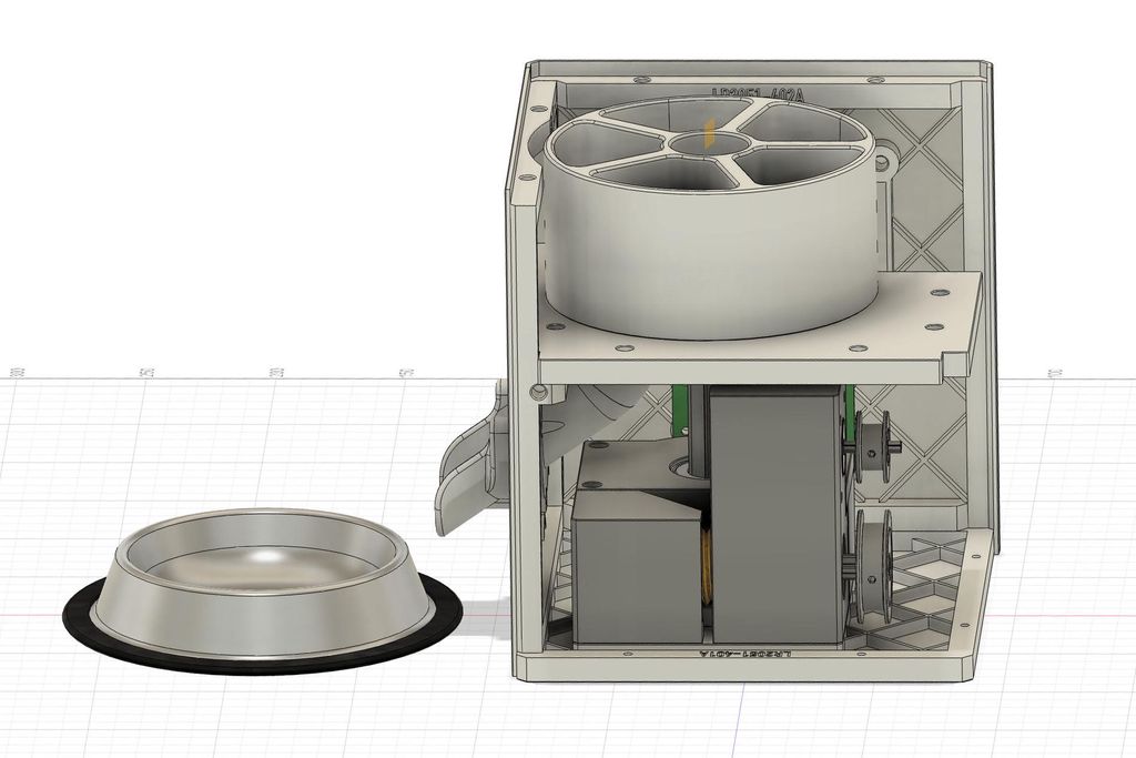
There is a turntable in the upper section of the device with five compartments. One of these compartments is aligned over the output funnel.
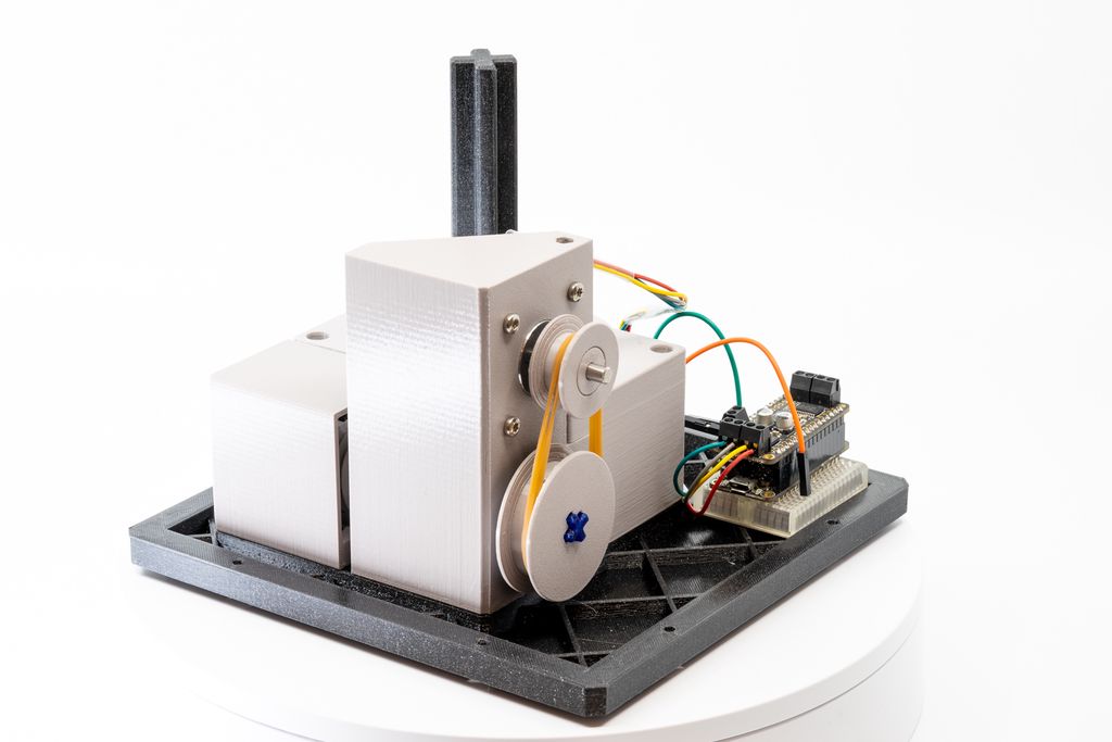
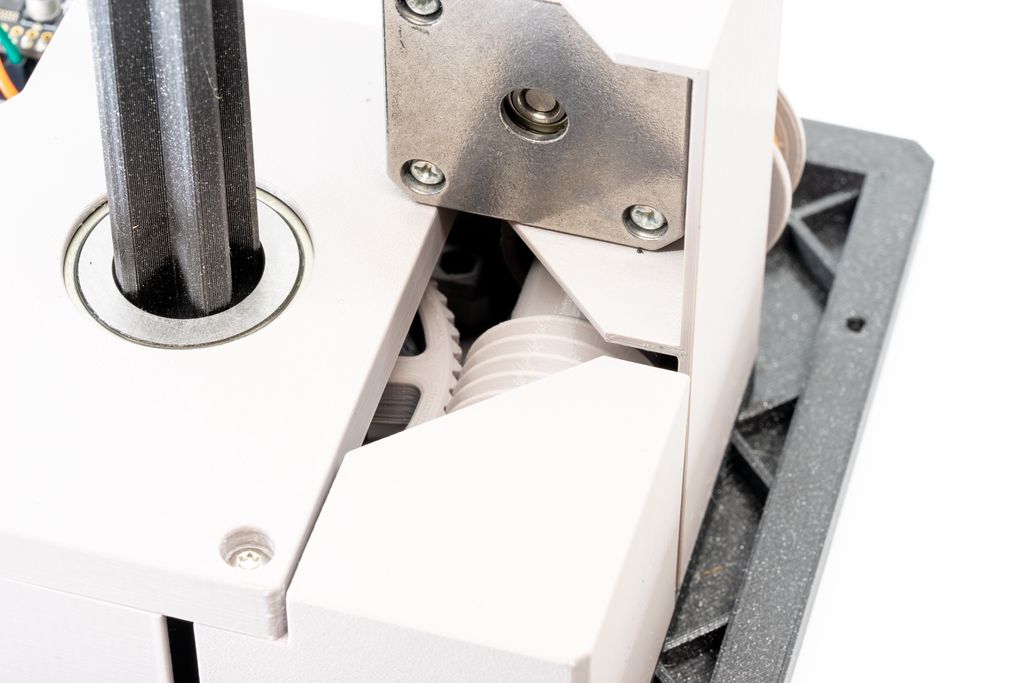
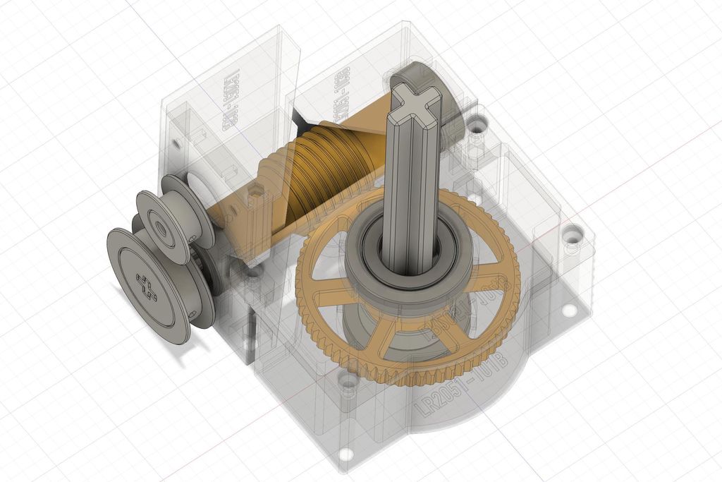
In the lower section is the gear box. It is a fully 3D printed worm drive, controlled using a NEMA 17 stepper motor.
Sensors
Under the platform, which has a transparent top layer, there are holes for sensors. Each compartment has a simple fill sensor using a IR LED and IR sensor. Also there is a position sensor, to align the turntable.
Interface Panel
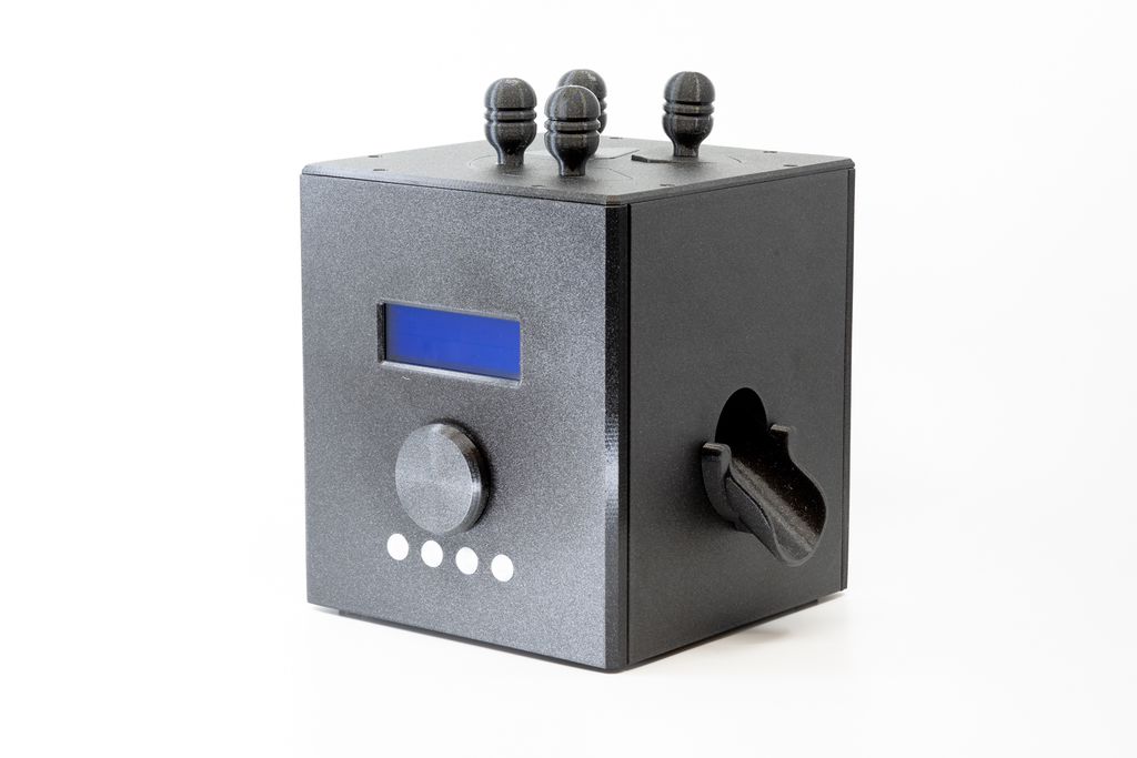
On the front side is an input panel, with a four lines LCD display and a rotary button for inputs. Below this button are four LEDs to display various states.
Mode of Operation
The working principle is very simple. You fill dry food or treats into the compartments, at a specified time, the turntable rotates and the food falls through the output funnel into the bowl.
My design uses sensors in each compartment to program the device, just be putting food into them. Imagine this implementation:
The first compartment is defined for the food while you are at work. If you fill it, the food gets dispensed at 2 pm.
The second compartment is for food if you work late and gets dispensed at 8 pm.
Without the sensor, the device would just rotate the turntable at 2 pm and 8 pm. This could irritate your pet, because, if it hears the sound of the rotating turntable, it expects a treat or food. Using the sensors, filling the compartments will “program” the device. So if you fill just the second compartment, the turntable will only rotate at 8 pm, even if you fill it in the morning.
This is just an example how you could implement your controller. It is your choice, if you add all these sensors, or just the position sensor.
Requirements
Required Mechanical Parts
M3 screws with flat heads in various sizes (8mm, 12mm)
NEMA 17 stepper motor with 5mm diameter D-shaft (almost any variant will work).
3D Printer Requirements
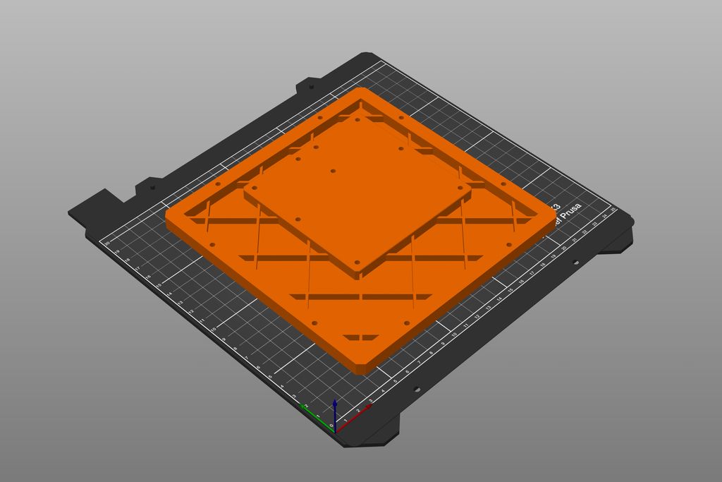
Largest parts are 180 × 196 mm, you need a printer bed matching this size.
0.4mm nozzle.
You can print PETG and PLA.
I recommend printing most of the parts using PETG, except a few parts which need to be printed with PLA, because of the stiffness. If you following this guide, I assume you have enough 3D printing experience to replace the materials with matching ones if you like.
Electronic Component Examples
The following components are the ones I use in the shown images. The panels for the enclosure have holes which fit these components perfectly. Feel free to use your own components and design your custom input panel.
Preheat the print bed and avoid a cold room temperature.
Carefully check for warping after print.
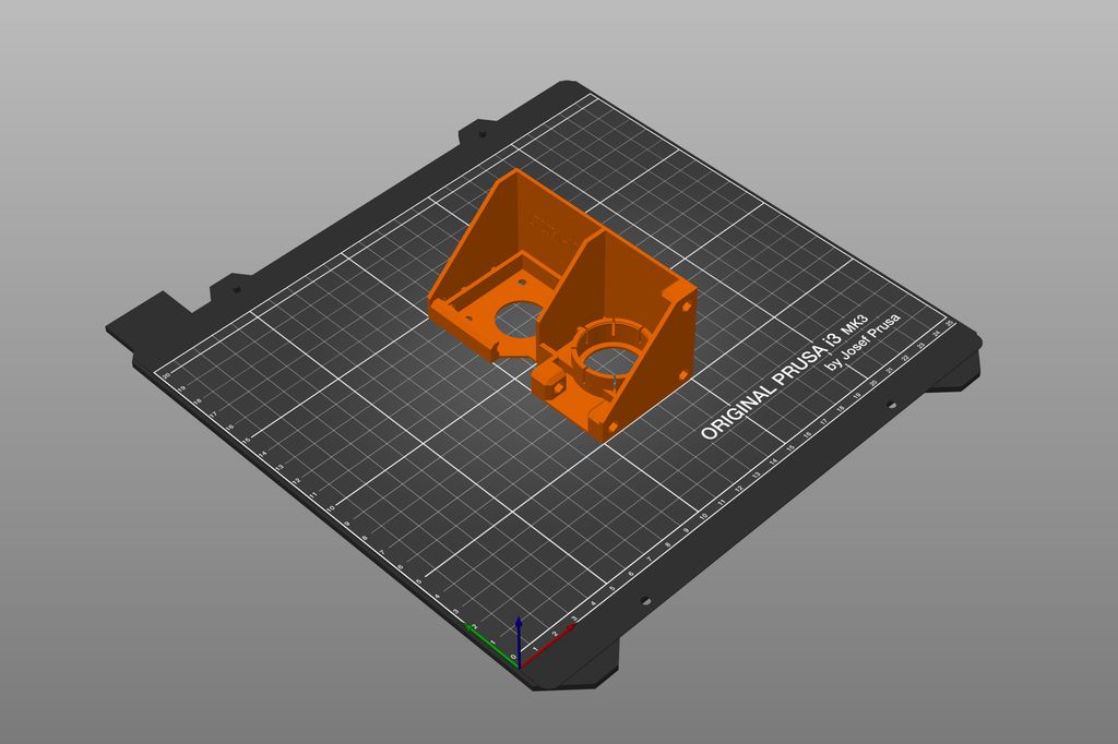
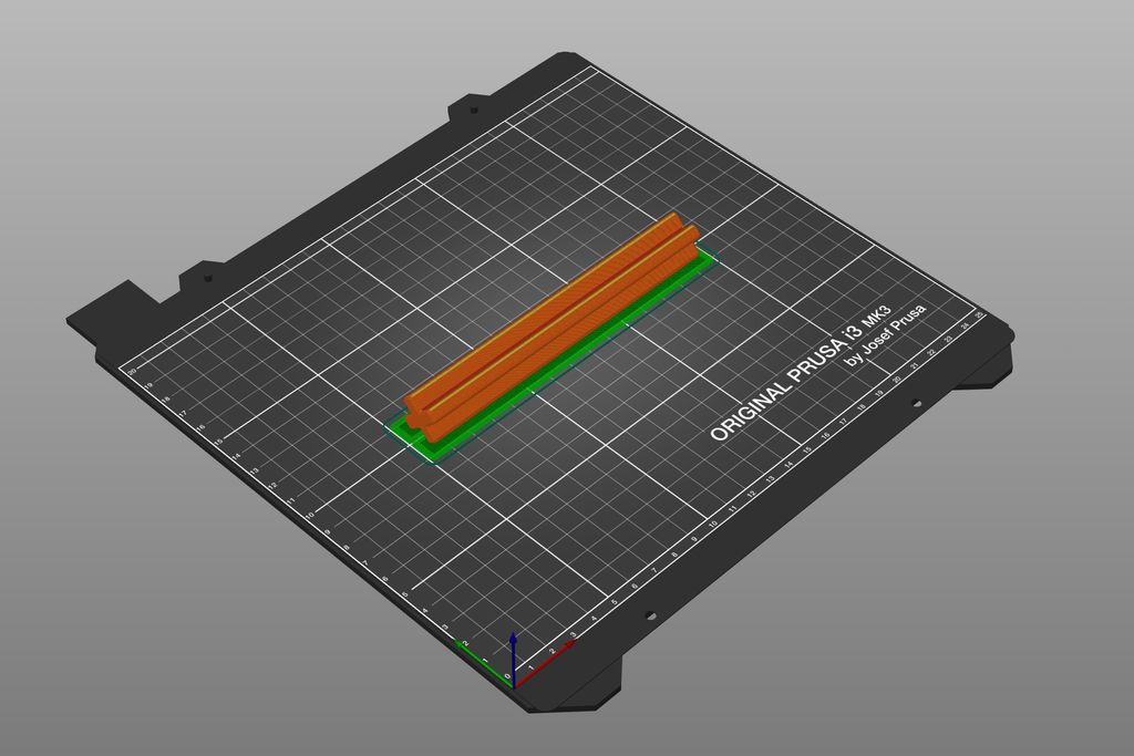
File: LR2051-108B.stl
Material: PLA (Galaxy Black)
Layer height: 0.1 mm
Print bed: Smooth
Supports: Minimum two raft layers
Difficulty: Hard
Notes:
Add a minimum of two raft layers.
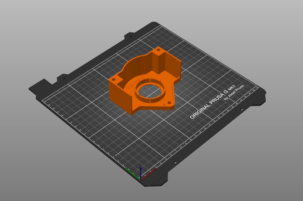
Make sure the axis is oriented as shown.
Preheat the print bed and avoid a cold room temperature.
Carefully check for warping after print.
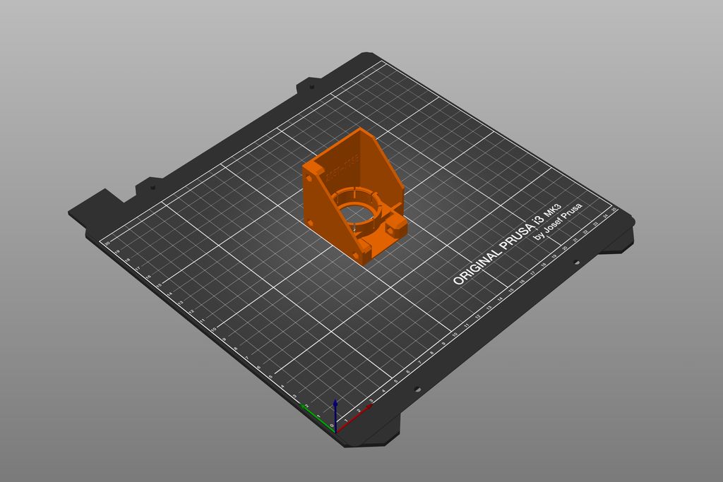
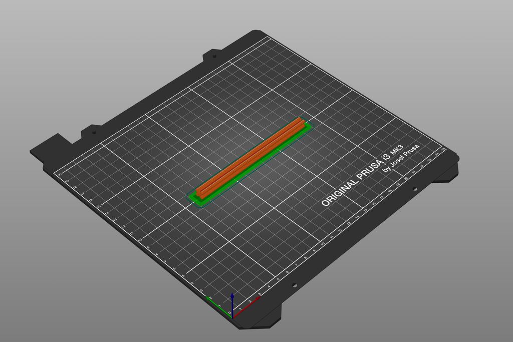
File: LR2051-111B.stl
Material: PETG (Urban Grey)
Layer height: 0.1 mm
Print bed: Powder coated
Supports: Add 10mm brim
Difficulty: Hard
Notes:
Add 10 mm brim.
Make sure the part is printed oriented as shown.
Preheat the print bed and avoid a cold room temperature.
Carefully check for warping after print.
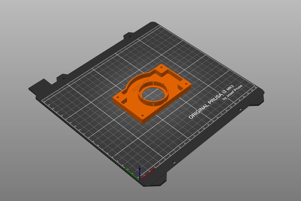
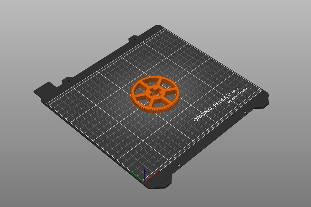
File: LR2051-112B.stl
Material: PETG (Urban Grey)
Layer height: 0.1 mm
Print bed: Powder coated
Supports: No supports required
Difficulty: Medium
Notes:
Preheat the print bed and avoid a cold room temperature.
Carefully check for warping after print.
Bearing Mockups
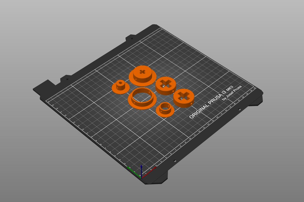
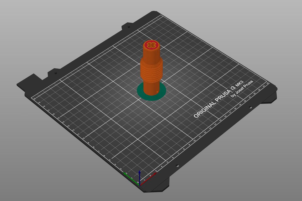
Optionally, you can print the bearing mockups, the files LR2051-821.stl and LR2051-822.stl. You can use them temporarily as replacement for the ball bearings.
Conclusion
This is the end of the first part. In the next part of this series, I will talk about the assembly and how to properly insert the insets into the printed parts.
If you have any questions, missed information, or simply want to provide feedback, feel free to comment below or contact me on Twitter. 😄
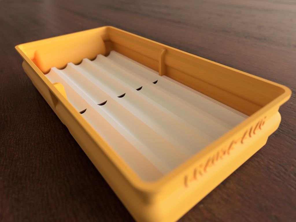
I created a parametric Fusion 360 insert template for the flat storage box series and included a drill-insert example, STL files, and OpenSCAD scripts. Download the free files, tweak the parameters to fit your tools, and read the full post for setup tips and examples.
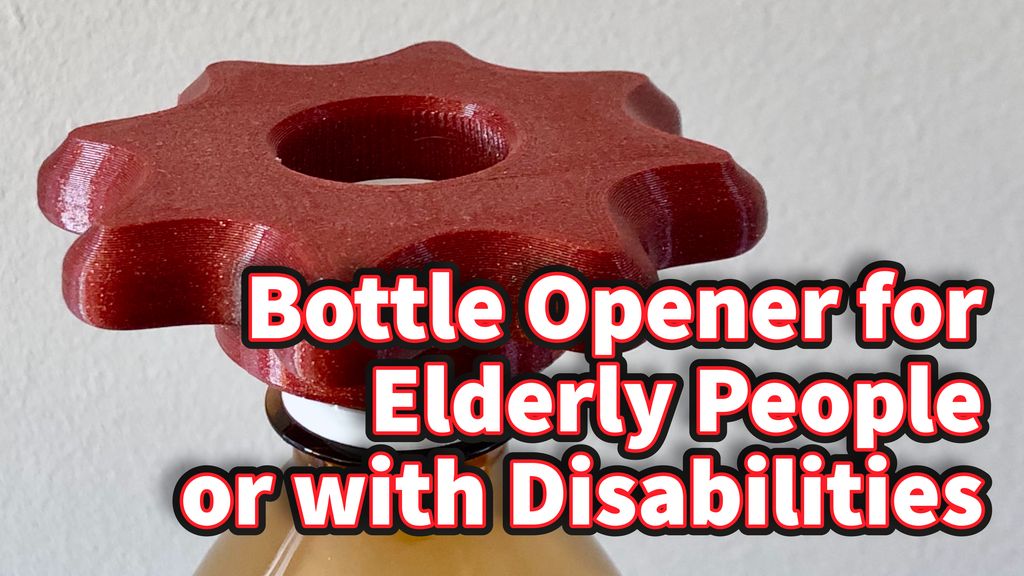
I designed a 3D-printable bottle opener to help seniors and people with limited grip turn 26–30mm plastic caps. The tapered 72-tooth socket adapts ±1mm and the handle has finger notches — print in PETG. Download the STL files and read the full post for print settings and tweaks.
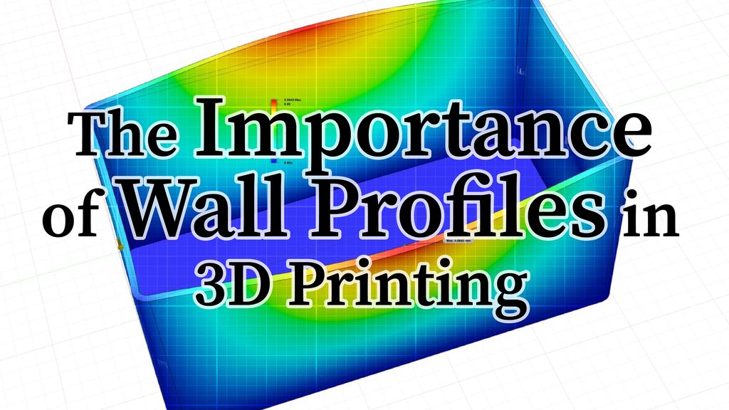
I'm not a 3D‑printing expert, but I show how simple wall profiles — correct XY/Z thickness, chamfers, and internal recesses — make printed boxes stronger and lighter. I share CAD steps, simulations, and common mistakes in plain terms. Read the full post for practical tips to improve your prints.
Posted on 2019-07-12— C++, Improve your Code, Learn
I walk through practical ways I use C++11's auto keyword to reduce repetitive declarations, simplify range-based for loops, lambdas and register access, and make Arduino and embedded code easier to refactor. Read the full post for examples and tips you can apply to your projects.
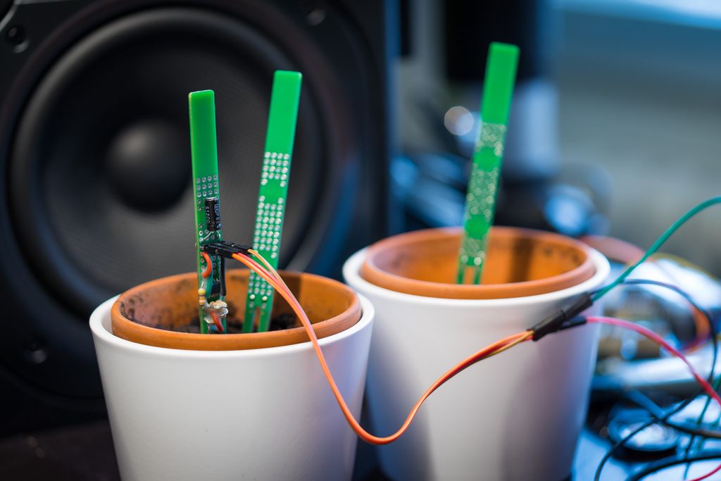
I walked through designing a cheap capacitive plant watering sensor, from goals and measurement options to component selection and early prototypes. I explain why I chose a CR2032‑powered op‑amp oscillator, ATtiny MCU and low‑power timer. If you’re curious, read the full post for details and test results.
I guide you through building a compact particle sensor node using a Raspberry Pi Zero W and a minimal custom shield, with published Gerbers, STL files and example code. I keep the design simple and extendable—if you'd like to build your own networked air-quality node, read the full post for parts, assembly and setup.