published: August 20, 2020 —
last modified: October 23, 2025
Recently I published a simplified version of the Always-On project hardware. Read this post for details. Today I publish a firmware example for the Always-On project.
This firmware is written for the PlatformIO environment using Visual Studio Code. It is using a special adaption of my HAL layer for PlatformIO using the Arduino layer for Adafruit Feather M0 boards.
I chose this approach, because it works on every operating system. Also, the Visual Studio Code development environment has code completion and all modern editor features one would expect. It works seamlessly with my HAL layer, to write rock solid and easy to understand code.
Clone the AlwaysOnWorkshop repository with all submodules: repository with all submodules: git clone --recurse-submodules [email protected]:LuckyResistor/AlwaysOnWorkshop.git
Open the project in Visual Studio Code from the PIO home page..
That is all you have to do. The required platform libraries for the project should be installed automatically after you open the project the first time.
About the Firmware Example
The firmware assumes the following hardware configuration:
The workshop light is attached to the (OUT) output.) output.
The switch in the workshop is configured as push button and attached at the (BTN) input.) input.
Two motion sensors are attached at S1 and and S2, rising the line from GND to V3.3 if motion is detected., rising the line from GND to V3.3 if motion is detected.
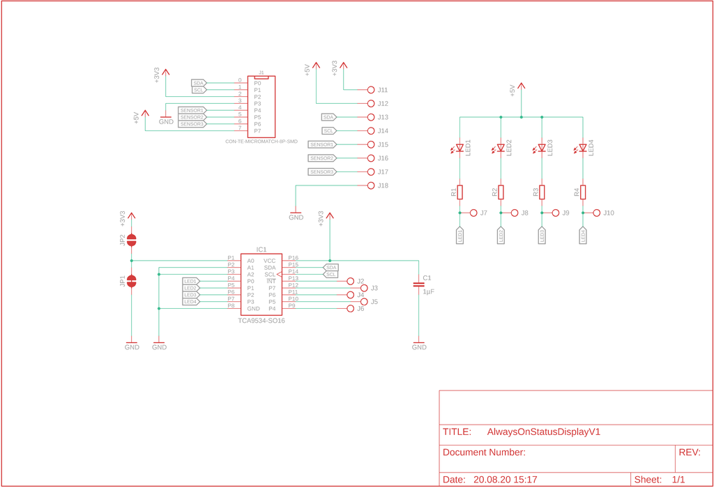
A simple four LED display is attached using a TCA9534 IO-expander chip on the IO-expander chip on the SDA//SCA pins. See the following schema: pins. See the following schema:
Usage
If you enter the workshop, the light is automatically turned on. If you leave it, it will automatically turn off after one hour.
To shorten the duration to turn the light off, you simply press the light switch once when you leave the workshop. If no motion is detected in the next 30 seconds, the light will turn off.
Conclusion
The provided example code should give you an excellent start for your firmware. The Always-On project is meant to provide a reliable bridge between the mains power installation and any smart controlling system.
If you have any questions, missed any information, or simply want to provide feedback, feel free to comment below. 😄
I ordered 'After Dark' PCBs from OSHpark for my pet-feeding device and wanted to share clearer, high-resolution photos so you can appreciate the black substrate with copper and transparent solder mask. If you’re curious about the look or details, please read the full post and leave questions or feedback.
I added a stable Hitachi LCD driver to the HAL layer, using an MCP23008 backend to cut wiring and simplify hardware. This post walks through parts, firmware repositories, and how to run the demo via serial shell. Read the full article for setup steps, code links, and usage tips.
I’ve released a major update to my 3D-print storage box system: expanded sizes (up to 6x6 and 9x9 split), improved geometries, 3MF files, JPEG previews, and more dividers. If you use my boxes or print them yourself, read the full post for download links, compatibility notes, and printing tips.
I've released several new 3D-print storage boxes with the label area moved to a different side so identical boxes can sit in a drawer with labels aligned. I explain size variants, rib adjustments, and how to download updated files. Please read the full post to see illustrations and the catalog link.
I've updated the flat boxes set with a refined wall profile (revision B) and added five new boxes, including a large 2×4 and four grid variants. I show corner comparisons and note existing customers received files. If this is useful, please check the full project details on the project page.
In part three I assemble and test the prototype PCB, set ATtiny13A fuses, and refine user interaction and firmware plans. I cover LED display choices, power measurements and a modular firmware approach. If you’re building a low-cost plant sensor, read the full post for practical steps and diagrams.