published: June 5, 2020 —
last modified: October 23, 2025
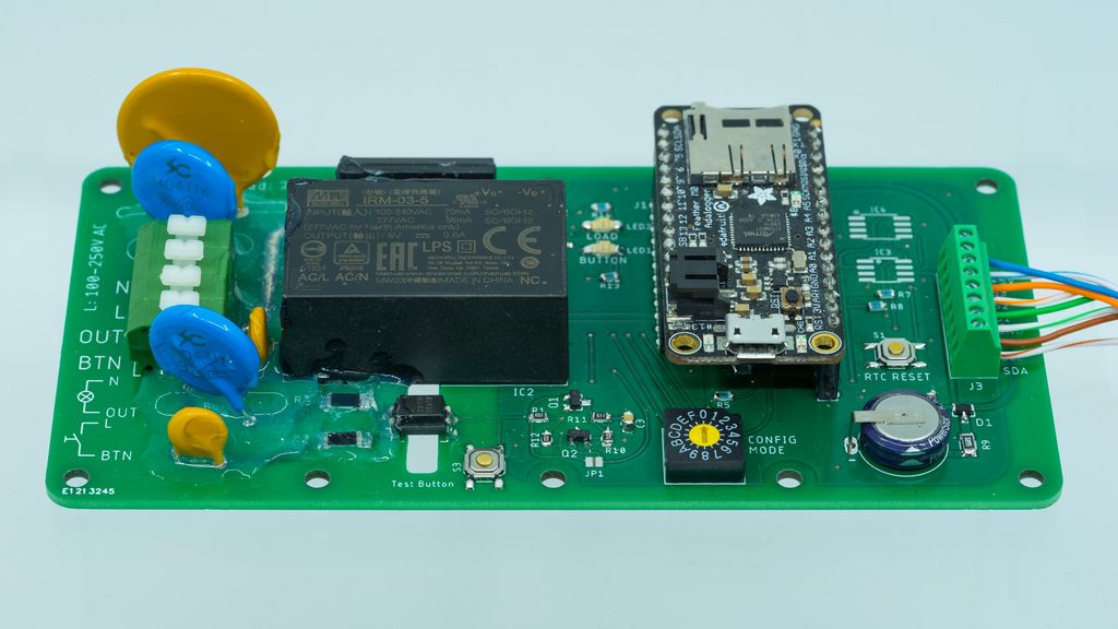
I just finished a new project, which is called Always-On. This project is a simple bidirectional bridge between the mains-voltage installation and an Adafruit Feather board as a controller.
The idea is to have a device integrated into the electric installation. It works as a smart light switch, monitors power lines or works as a timer for a device.
In this post, I describe a minimal version of the project I used as a prototype, which has one power sensor and one solid-state relay. It may be a good starting point if you plan to create a similar device.
In contrast to other projects, I will do only a superficial overview in this post. It is no project to be copied as shown. This post is meant as inspiration providing a working base to start.
Overview
Let’s have a look at the different sections and components of the device.
Mains-Voltage Side
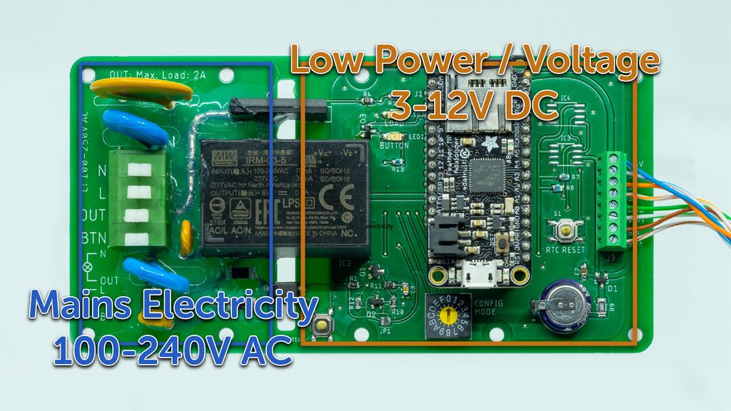
The left side of the board is connected to mains power and the right side is the low power side with the controller. There is a large air gap between the two sides as extra protection.
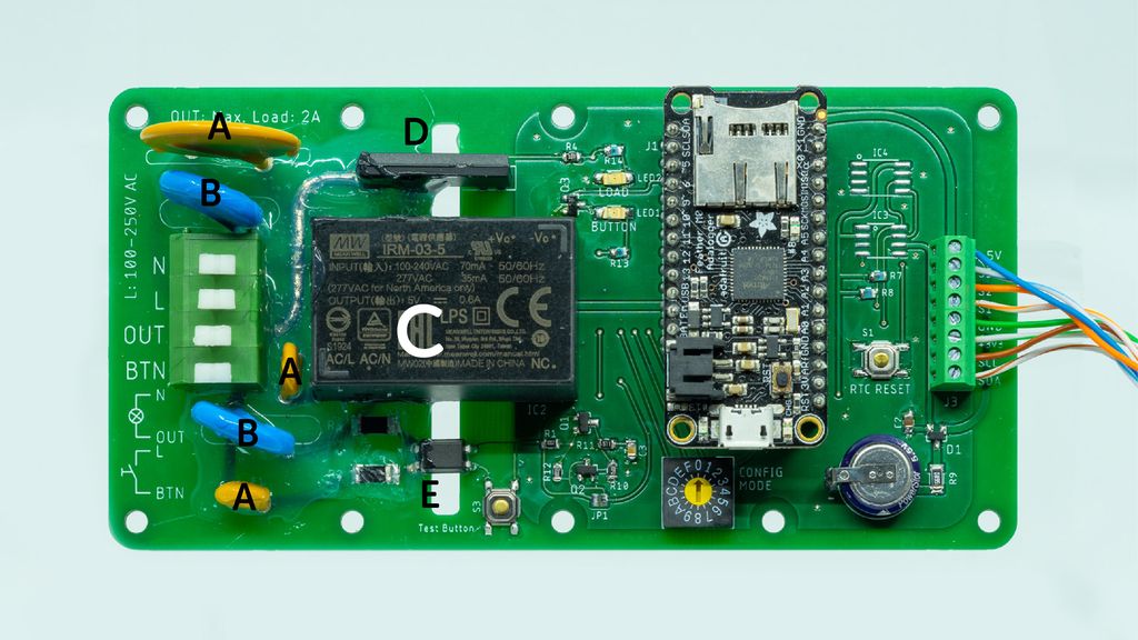
There are three fuses (A) and two over-voltage protections (B) as an extra safety measure. A power module (C) IRM-03-5 from Mean Well converts mains-voltage to the required 5V DC for the controller part. The traces on the top and bottom side are covered with insulating silicone.
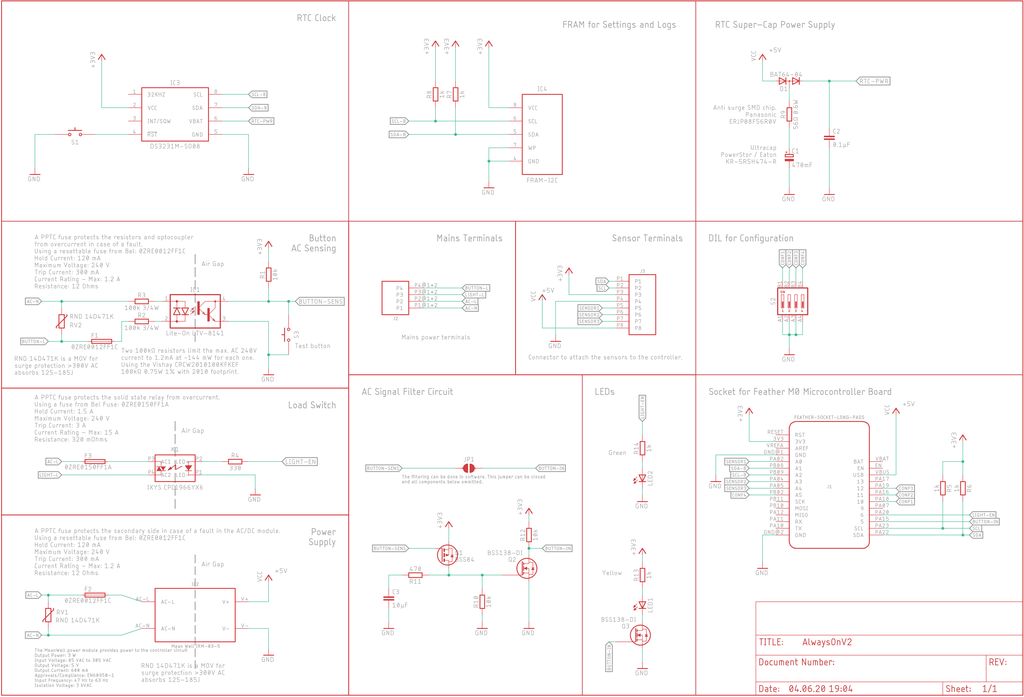
On the upper side is the solid-state relay (D) IXYS CPC1966YX6, which can switch a load up to 3A. On the lower side is the optocoupler (Lite-On LTV-8141) for sensing line power. I use two 100kΩ 3/4W resistors to reduce the voltage for the optocoupler to the required value.
Controller Side
The right side of the board is built around a socket for any Adafruit Feather board. The shown minimal version has 5V as main power supply, the Adafruit Feather provides the 3.3V power from this source.
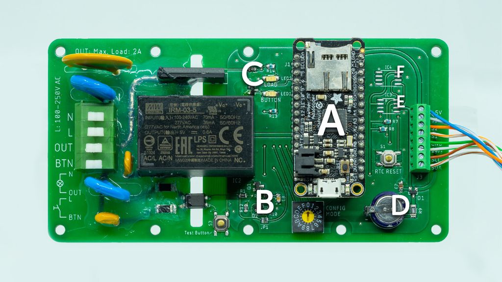
I use an Adafruit Feather M0 Adalogger (A) in this example, any other Feather will work too. You can add boards with WiFi, Bluetooth or LoRa and use Feather Wings on top.
On the lower side is a small debounce circuit (B) for the optocoupler signal and on the upper side, two LEDs (C) for displaying the current state of the power sensing circuit and solid-state relay.
There is a footprint for a DS3132M RTC chip (E) and a super capacitor (D) as backup power. The footprint (F) is for an optional FRAM chip to store settings or logs.
Extension / Sensor Connector
The connector on the very right side of the board is for connecting sensors and extensions. It provides 5V and 3.3V power, connection to three microcontroller pins and a separate I2C bus.
Circuit Schema
The following schema is for the shown version of the device.
Specific part numbers are only noted if they are important and the result of calculations, otherwise, common components for resistors, capacitors and LEDs will do.
Testing
I designed the device to do tests without connection to mains-voltage. The mains-voltage part is disconnected and the controller side is powered using the USB connector on the Feather board.
Now just the controller side is powered and you can use the test button to simulate the power sensing via optocoupler and monitor the state of the solid-state relay using the LEDs.
This is a very safe way to develop a firmware for the controller, without all the risks of mains electricity connected.
For deployed devices, you simply remove the Feather board and work on the firmware with the test board, not connected to mains-voltage. After finalising the new firmware version, you put the feather back into the device.
Housing
Housing is very important. I designed the board to fit into an IP65 sealed case using two cable glands on both sides. There has to be enough space in the housing for free air circulation.
If you are unsure about the heat dissipation, just add a temperature sensor to your device and use it to monitor the temperature rise in some extreme situations. E.g. use a hairdryer to simulate a hot summer day. 😁
Conclusion
A controller as shown provides a permanent solution for home automation. With your custom firmware, you control lighting or other devices in complex ways, without WiFi, Bluetooth and smartphone required (aka. IoT).
If you have any questions, missed any information, or simply want to provide feedback, feel free to comment below. 😄
Posted on 2020-11-21— 3D Printing, Common, Projects
I've been reorganising my lab and designed stackable organiser boxes optimised for fast 3D printing. They use a 60×60mm raster, stabilising walls, dual label slots and rail grids. I offer a free STL subset and explain print settings—read the full post for downloads and the complete shop set.
I’ll walk you through creating custom patterns for your snowflake decoration, covering double-buffering, frame-sync, non-linear PWM, fixed-point math and the scene interface in C++. If you can solder and use an SWD programmer, read on for practical examples and a ready-to-edit User scene template.
I explain why I add small guide bridges to tricky gaps in my 3D prints and how they help PETG bridging. I show the settings I use and demonstrate results in my modular lantern model. Read the full post to see images and step-by-step tips to apply this to your designs.
I recently updated my storage-boxes system to include split boxes so you can print larger containers or use small printer beds. I tested glued joints with PLA and PETG and added 12 new STL parts. Read the full post to see part numbers, joining tips, and where to download them.
I walk you through using the RP2040's PIO to measure a PC fan's RPM with a small software filter to ignore short spikes and timeouts. I explain the PIO routine and a simple RpmInput wrapper in MicroPython—read on if you'd like the code and practical setup tips.
Posted on 2019-07-13— C++, Improve your Code, Learn
I explain why I prefer #pragma once over macro header guards and how it prevents subtle build errors and wasted debugging time. I’ll show examples, common pitfalls, and practical steps to replace guards in existing projects — read on if you want a simple, low-risk improvement.