published: December 7, 2019 —
last modified: October 23, 2025
In this article, I will discuss how to write custom patterns for your snowflake decoration. This is a rather advanced topic, and there are a number of prerequisites that are required and listed below. Nevertheless, it is rewarding to you see your very own pattern displayed on the decoration.
You must solder a 5-pin programming header to all snowflake boards you wish to reprogram, which is not included in the kit from Pimoroni.
An SWD programmer is required to write the firmware to the microcontroller.
Established C++ language knowledge.
If you are still with me at this point 😆, please read “Programming the Snowflake Decoration” if you have not already done so. The article describes the basic setup of the toolchain required for reprogramming.
Table of Contents
First, Some Basics
Blinking a single LED is easy — displaying a smooth animation is not.
In the firmware, I use a number of techniques to optimize the display:
Double-buffering
Frame-synchronization
Non-linear PWM
Frame-based animation system
Fixed point math
Double-Buffering
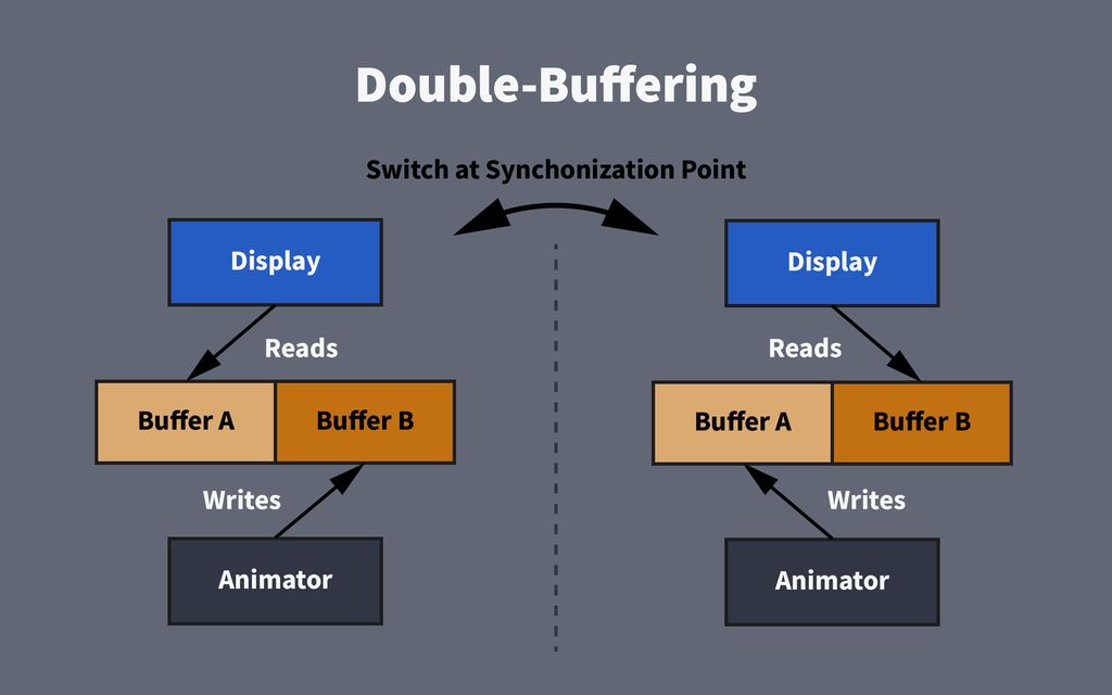
You want to implement double-buffering to prevent incomplete data from being displayed. This is a very simple technique, and is most effective with frame synchronization.
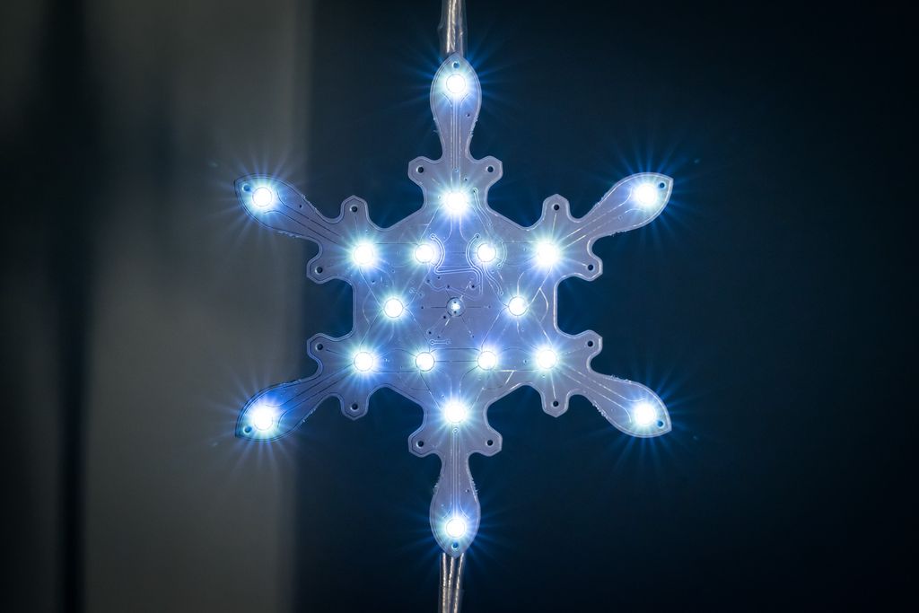
Check the Display.hpp and Display.cpp files from the snowflake firmware. This code implements software PWM using an interrupt to control the brightness of all 19 LEDs. The code reads a value from a buffer with 19 bytes. Each byte represents the brightness-level for a single LED.
Without double-buffering, you will experience many undesired side effects.
Imagine this situation: All LEDs are off and you are about to turn them all on to full brightness. You start to write the full brightness values to the buffer, but your code is interrupted by the display interrupt. Only the first ten values were written to the full brightness, and the nine remaining are still zero.
The first ten LEDs are turned on by the display interrupt handler code. After the interrupt, the processor returns to your code and writes the remaining nine values. For a short period, there was an incomplete frame visible on the decoration.
If this happens once every minute, it is likely that nobody will notice it – but if this happens 20-30 times per second, the displayed animation will look rather strange. In certain situations, if the animation code has even a slightly different frequency than the display code, you will see noticeable side effects on the display.
Double-buffering solves this problem.
Double-buffering helps solve this problem. You can simply use two buffers. One buffer is displayed and one is prepared for display. If all writing for one buffer is complete, the display will then switch to the new buffer.
Frame-Synchronization
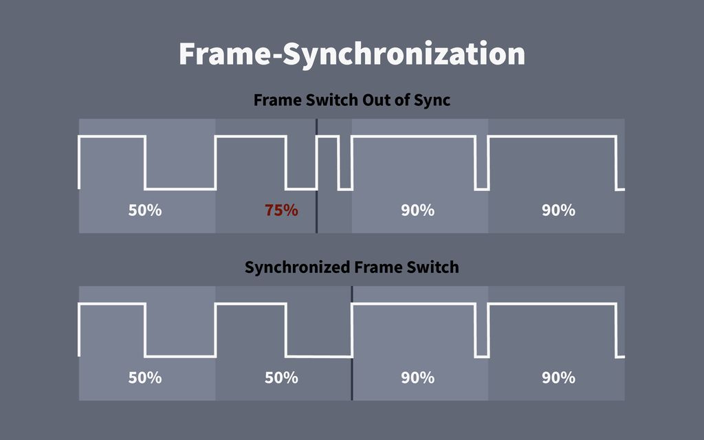
We implement frame-synchronization to switch between the two buffers at a defined point in time.
This illustration displays a program that switches an LED between 50% and 90% brightness. If the switching is not synchronized, you get a mix between the two PWM values.
At first glance, you may think this is rather useful. It will add intermediate values to the animation, which smoothes quick changes. If you just slowly blend between brightness levels, this can be the case. Yet, if you try to create sparkling effects, these intermediate values will kill the effect.
Non-linear PWM
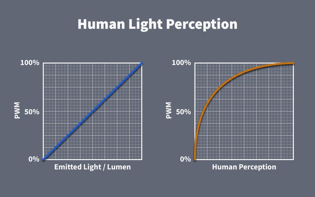
Thanks to rhodopsin in the rods of the retina in your eyes, your brain can detect very small amounts of light. To optimize night vision, the perception of brightness levels is not linear, but somewhat logarithmic.
If you drive an LED using PWM and measure the emitted light in lumens, you will obtain linear results. An LED emitting 500lm when fully powered will emit 250lm with a 50% PWM ratio.
However, your perception of this brightness is very different. You will observe a large difference between 1% and 2%, but it will be difficult to differentiate between 90% and 91%.
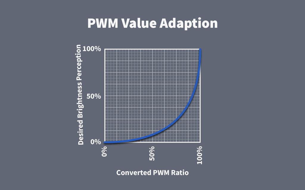
If you look at this problem superficially, the solution is simple. You can simply create a conversion table to adapt to the logarithmic perception.
Let’s do some 8-bit math: You would like to have 64 brightness levels, from zero as black to 64 as fully on. To prevent any visible flickering, you run the software PWM at a high frequency, which supports 64 PWM levels.
Adjusting the brightness perception requires a formula such as:
[latex]\text{pwm} = \frac{\text{level}}{\text{num of levels}}^3 * \text{num of levels}[/latex]
As you can see, this leads to a long series of zero values at the beginning of the table. You would need at least a 16bit resolution for your LED PWM implementation to get the required precision.
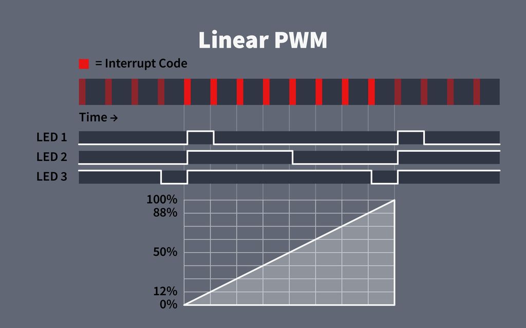
For linear PWM, you set a timer to a regular interval. An interrupt is triggered in the defined interval which controls the LED outputs.
This illustration shows a very simplified system with only 9 different brightness levels. The red bars at the top of the timeline represents the executed interrupt code.
This is the more straightforward way to implement PWM on a microcontroller if there is no dedicated PWM peripheral for all outputs. In the case of DMA support, the interrupt code is replaced by a large bit-table — but the core principle remains the same.
To avoid perceptible flickering, the PWM frequency should be greater than 400Hz. If you want to provide 256 brightness levels at this frequency, the interrupt must be called 102’400 times per second, at 102.4kHz.
Now, consider a microcontroller executing ten instructions per microsecond (e.g. running at 10MHz). At 102.4kHz, it could only execute approximate 90 instructions in the interrupt – and this would use the full capacity of the processor without any room for other code.
To solve the performance problem, you can either lower the overall frequency of 400Hz, and risk perceptible flickering, or lower the number of levels with poor stepping in the dim brightness levels.
Pros
Simple implementation.
Not very time-sensitive.
Cons
Brightness adaptation required.
More brightness levels required due to the adaptation.
Many brightness levels are not used because of the adaptation.
Uses a large amount of CPU time for the interrupt if not implemented via DMA.
Non-Linear PWM
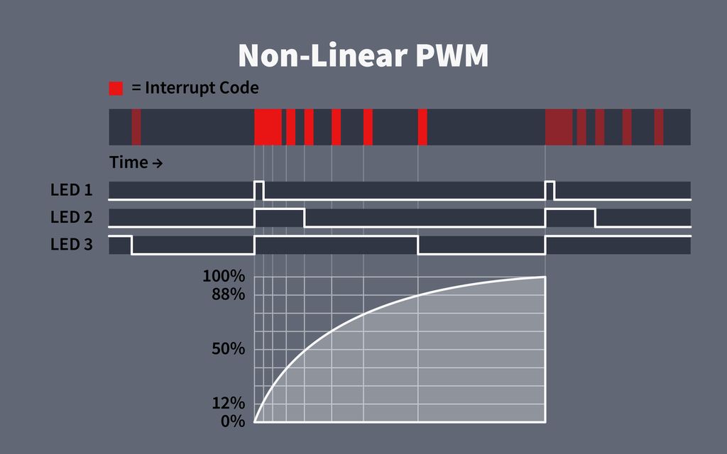
With non-linear PWM, you utilize a precise timer for the interrupt dynamically.
At the start of each interrupt, a new dynamic timing to the next interrupt is set, which creates a logarithmic timing behaviour.
As you can see, at very low levels, the timing between the interrupts would be too short without overlapping. This is solved by merging the first levels into one initial interrupt block.
Pros
Dim brightness levels are possible.
No adaptation of levels required.
Fewer brightness levels required.
Less interrupt code executed.
Cons
Complex implementation.
Time-sensitive interrupt.
Frame-Based Animation System
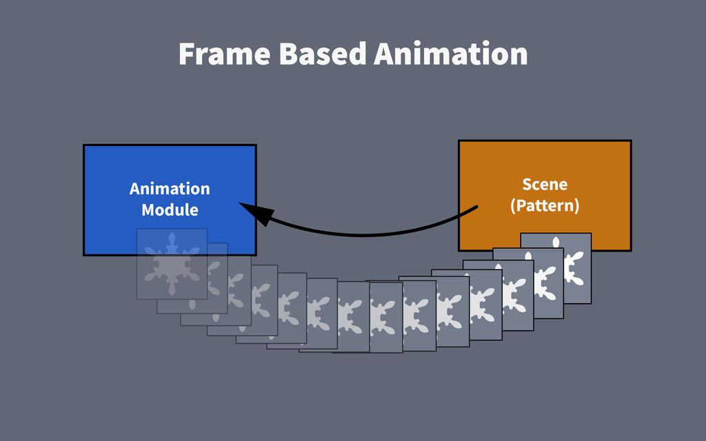
Many different patterns (called Scene in the code) are integrated in the firmware. In Random Mode, one pattern will blend smoothly to another. This is possible using a highly abstract, frame-based animation system.
Code generating only an effect (scene, pattern) must provide a sequence of frames with the new states for all 19 LEDs. Each call has to provide the next frame in the sequence, just like a video stream.
This makes the scene code completely independent from the rest of the system, meaning it is free from any dependencies. Effects can then be implemented in a very simple, abstract way.
The animation system in the snowflake decoration runs at ~32 frames per second, allowing for very smooth effects.
Fixed Point Math
Cortex-M0+ chips have no hardware support for floating-point numbers. For best performance, you must stick with integer calculations. However, there is a good compromise between these two worlds, called fixed-point math.
The class Fixed16 is located in my HAL layer, and is also contained in the snowflake firmware. It implements a 32-bit fixed-point value with a 16-bit fraction part. You can use it like any floating-point value, but calculations are completed nearly as fast as integer math.
Using this class, we can represent brightness levels as values between 0.0 and 1.0, where 0.0 is off and 1.0 is full-on. This has many benefits:
It is an abstract system in which you do not need to know the actual number of brightness levels of the system.
Because of this abstraction, any effect can easily be ported to another implementation with more or fewer brightness levels.
Calculations to mix and blend frames are simple and precise.
Interpolation between values, used for any smooth transition, is straightforward.
Where to Start
Be sure to download the latest version of the firmware, 1.2.2. It contains a template scene for a quick start.
The files src/scene/User.hpp and src/scene/User.cpp contain the User scene, which is already integrated into the firmware. Go ahead and modify the code in these files for your first experiments.
The Structure of a Scene
An effect or pattern is called a scene in the firmware. A scene is no class, but rather a well-defined interface in a namespace.
namespacescene{namespaceUser{/// The number of frames for this scene
///
constFrameIndexcFrameCount=1216;/// The function to initialize this scene.
///
voidinitialize(SceneData*data,uint8_tentropy);/// The function to get a frame from this scene.
///
FramegetFrame(SceneData*data,FrameIndexframeIndex);}}
Each scene is found in the namespace scene and defines its own namespace with the name of the scene. In this case, the second namespace is called User.
The interface is defined in the header file User.hpp and must consist of the following three elements:
A const variable cFrameCount with the number of frames in the scene. with the number of frames in the scene.
The initialize function, which is called once before a scene is displayed. function, which is called once before a scene is displayed.
The getFrame function, which is called ~32 times per second to obtain the next frame of the scene. function, which is called ~32 times per second to obtain the next frame of the scene.
Here, you see a minimal example implementation in User.cpp. In this example, the initialize function is not used and remains empty.
In the getFrame function, a black frame is created with the line Frame frame;. Next, the for loop assigns new values to this frame which is returned in the last line.
The parameter frameIndex of the getFrame function is incremented for each call. In the current example code, from zero to 1215, then the counter will start over at zero. The number of counted frame indexes is modified using the cFrameCount constant in the header file.
Enable Testing Mode
Open the file Configuration.hpp. You will see that it contains various configuration variables for the firmware. Now, search for the following line:
constboolcStartWithUserScene=false;
Set the value to true:
constboolcStartWithUserScene=true;
If you compile the firmware and run it on the snowflake board, it will start directly with the User scene.
The Frame
Remove the example code from the getFrame function and replace it with this code:
The LED indexes in each frame are arranged as shown in the following figure:
By assigning a PixelValue to individual frame indices, you set the brightness of these LEDs. A pixel value lies within the range of 0.0f and 1.0f. Here, 0.0f is black and 1.0f is maximum brightness.
Add an Index-Based Animation
The simplest way to create an animation is by using the frame index, on which you will base the animation:
Implementing custom animations is relatively straightforward thanks to the extensive animation framework that already exists in the firmware. You can create numerous interesting effects, even with just a few lines of code.
Go ahead and start experimenting with simple animations and take a look at the existing scenes, which use slightly different animation techniques. In the next part of this series, I will explain some of these in more detail.
If you have any questions, missed any information, or simply want to provide feedback, feel free to comment below or reach out to us on Twitter!
I wrote a concise page about my Snowflake project from late 2017, sharing open-source hardware designs and base firmware. If you have some electronics experience, you can build your own boards — it's a rewarding decoration. Read the full project page for files, repo links, and leave any feedback or questions.
I present a stylised logic-gate puzzle: a circuit that performs a handy function. Try to deduce what it does from the diagram, use the hints if you get stuck, and read the full post for the solution and explanation. I'd love your feedback or questions.
I describe making a small alpha batch of my low-cost plant-watering sensor: ordering parts, prepping and soldering wires, testing PCB assembly with stencils, and solving sealing with epoxy. If you’re interested in practical prototyping tips and lessons learned, please read the full post for photos and detailed steps.
Posted on 2018-08-31— C++, How and Why, Improve your Code
I often encounter poorly written C++ libraries, especially around hardware. In this post I outline four practical strategies—rewrite, refactor, wrap the library, or wrap the interface—to regain control, improve reliability, and reduce pain. Read on for pragmatic steps and examples you can apply to your projects.
I walk you through using the RP2040's PIO to measure a PC fan's RPM with a small software filter to ignore short spikes and timeouts. I explain the PIO routine and a simple RpmInput wrapper in MicroPython—read on if you'd like the code and practical setup tips.
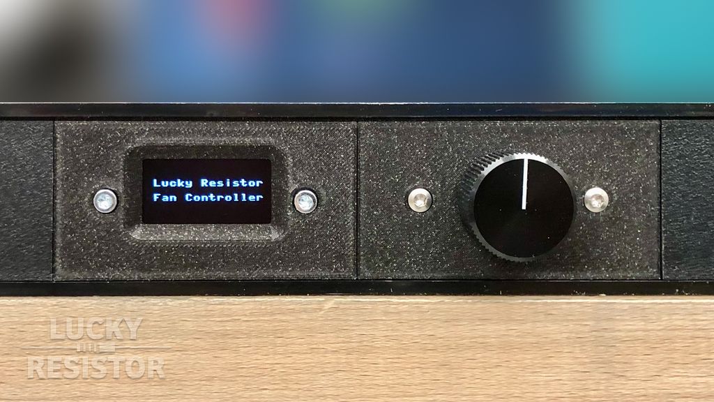
I migrated several servers into a compact 19-inch rack and reworked my Arduino Uno fan controller to fit a 1U RND enclosure. I show choosing the case, adding a rotary encoder and filter circuits, testing signals, and 3D-printing panels. Read the full post for STL files and build notes.