published: November 30, 2019 —
last modified: October 23, 2025
In this brief article, I will discuss the requirements to flash a custom firmware to your Pimoroni snowflake decoration. I assume you have some programming knowledge and have previously worked with an Arduino Uno or Adafruit Feather.
Table of Contents
Required Hardware
For the Pimoroni version: 5 pin programming header. One for each snowflake.5 pin programming header. One for each snowflake.
SWD programmer.
Jumper cables or adapter to connect the programmer to the header.
5-Pin Programming Header
There are several options for the programming header. First, you can buy matching ones:
A cheaper solution is to use a regular through-hole header and bend the pins to a 90º angle. I tried this, and it is working really well. You can either use a male or female header with a pitch of 2.54mm.
The SWD Programmer
You need a special device, called a programmer, to write the firmware into the flash of the microcontroller. There is no bootloader on the chip, nor any serial or USB port prepared for firmware upload.
To accomplish this, I recommend using a J-Link programmer from Segger. These programmers are very robust, easy to use, and work well with a wide range of protocols and microcontrollers. For private use, a cheaper version, the J-Link Edu Mini, is available for $18-$20. You can purchase if either through various distributors, or directly from the manufacturer in the US.
There are many other SWD programmers available on the market, and you can even use a Raspberry-Pi with OpenOCD for the task. Here, I will focus on the Segger solution, primarily because it requires little knowledge and is reliable and fast.
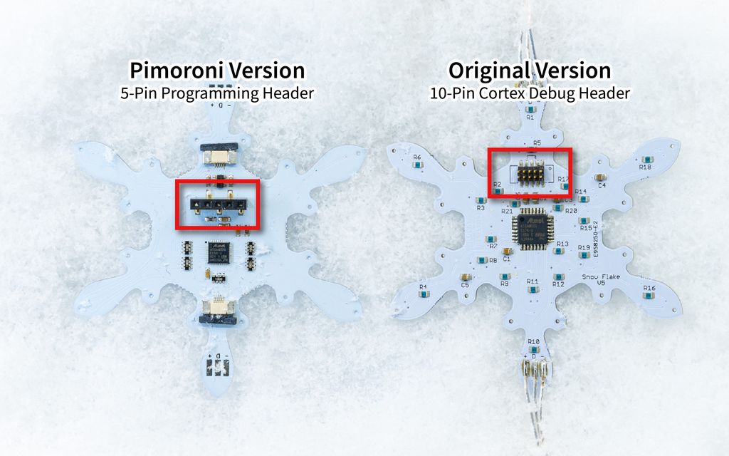
Start by soldering the programming headers to your snowflake boards, if not already done. The next illustration shows the location of the programming header on both board versions.
2. Install Atmel Studio
You will need Atmel Studio to compile the firmware from the source. Simply download the setup from the Microchip website and install it.
I recommend accepting all default values in the setup. Here I only point out important decisions of the setup. Unless otherwise noted, stick with the defaults.
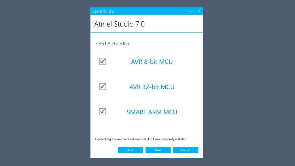
After accepting the license agreements and choosing the install location, you should see this screen:
Go ahead and check all platforms, even if you only need the 32-bit version. Then click Next.
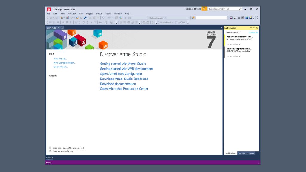
Now, start Atmel Studio and check for any updates in the notifications:
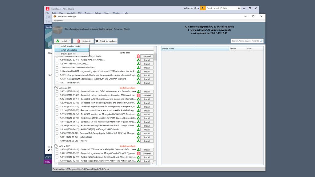
Open the device pack manager (Menu Tools) and select Install all Updates:
Close the application before proceeding to the next step.
3. Install the J-Link Software
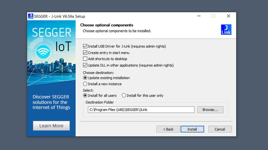
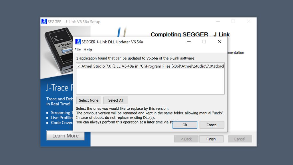
Next, download and install the latest J-Link software.
You can click the Clone or Download, which will allow you to download the latest version of the repository as a ZIP file.
Now, you can extract all files and directories from this ZIP to your desired location, e.g. the “Documents” folder in your installation.
5. Connect the Programmer to the Board
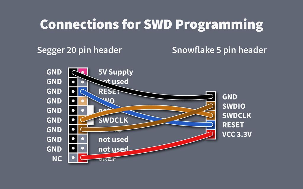
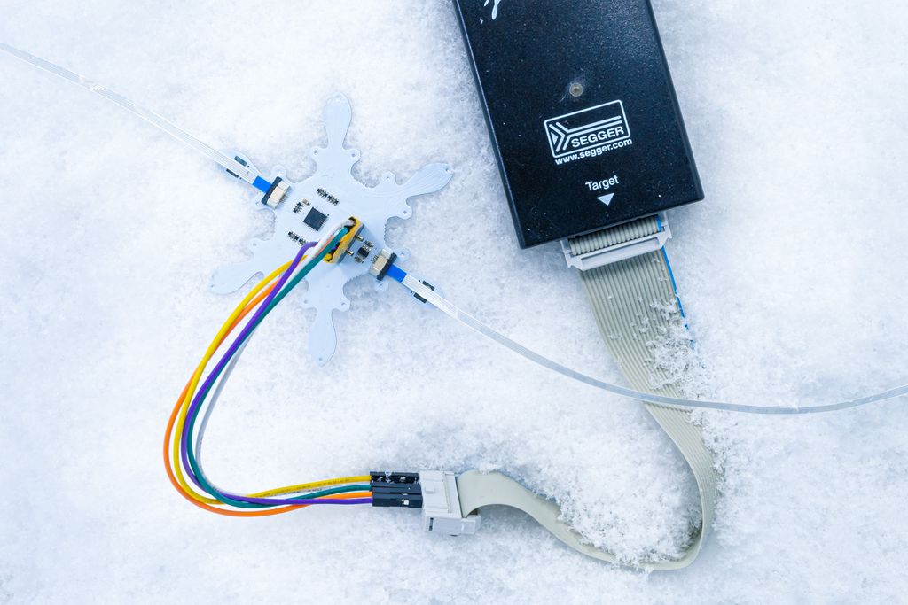
Now connect the programmer to the programming header of the board. Make sure you connect all five signals:
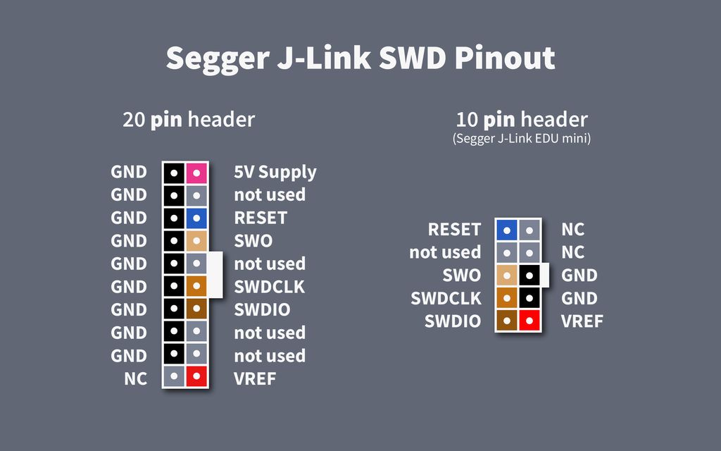
On the programmer side, for SWD programming, the signals are assigned as shown in the next illustration. Here it shows the assignment if you look at the male connector with the pins.
It is best to use jumper cables to make all connections. Keep the wire lengths as short as possible, but lengths less than 50cm (20″) should function without issue.
The following setup is acceptable:
Test your Setup
Now is the time to test your setup. Before we start, I want to note two important things:
While programming, the snowflake board must be powered.
A programmer will not power your board while programming. The connection between the +3.3V pin on the snowflake and VREF at the programmer is used to measure the voltage and set the logic level.
Therefore, you must power your snowflake decoration using the USB connector. Once programming begins, the microcontroller is stopped and restarted shortly after.
Connect the snowflakes and the programmer to the same USB hub or computer.
When connecting the grounds of the snowflake and the programmer, be careful and ensure these grounds have no large potential difference. Otherwise, this will create a ground loop, which will trigger many problems.
To stay on the safe side, connect the programmer and the snowflake boards to the same computer or USB hub.
1. Check the Wiring
Verify the following:
The snowflake boards are powered and sparkling.
The programmer is connected via USB.
The programmer is connected to the snowflake as shown above.
There are no shorts, and no smoke… 😉
2. Open the Project in Atmel Studio
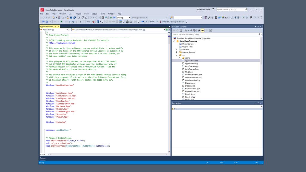
Next, open the file SnowFlakeFirmware.atsln from the downloaded firmware with Atmel Studio.
If double-clicking this file does not work, first open Atmel Studio, then use “Open…” inside the studio to open the file.
Now, the application should look more or less like this:
3. Select your Microcontroller
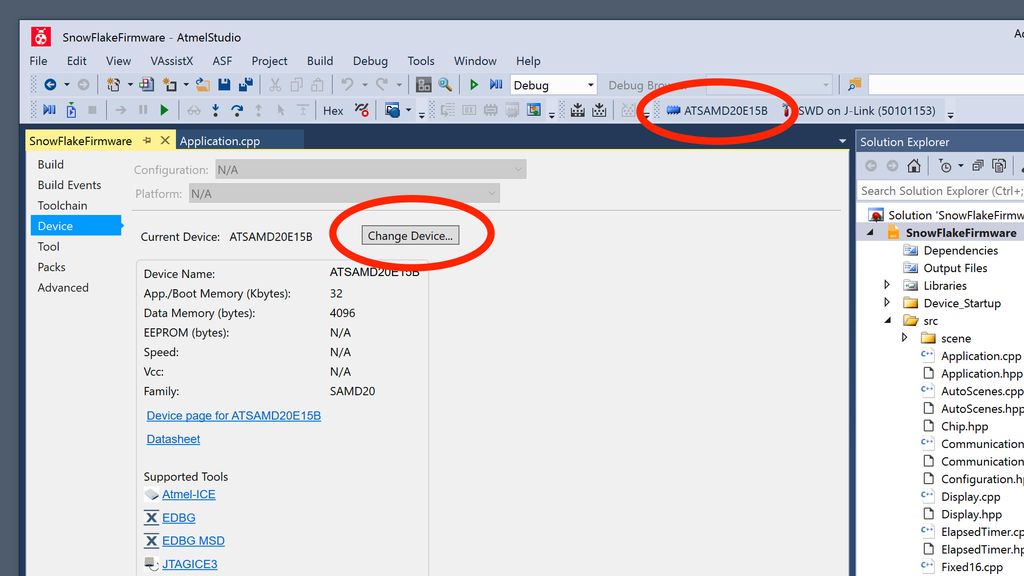
Select the right microcontroller for your project:
For the original snowflake: ATSAMD20E17A
For the Pimoroni version: ATSAMD20E16B
If you are not such which version you have, just check the number printed on the microcontroller on your board.
The microcontroller is displayed in the toolbar. You can change it by clicking this button and Change Device…. It will then replace a number of files in the project – which is perfectly fine.
4. Select the Programmer
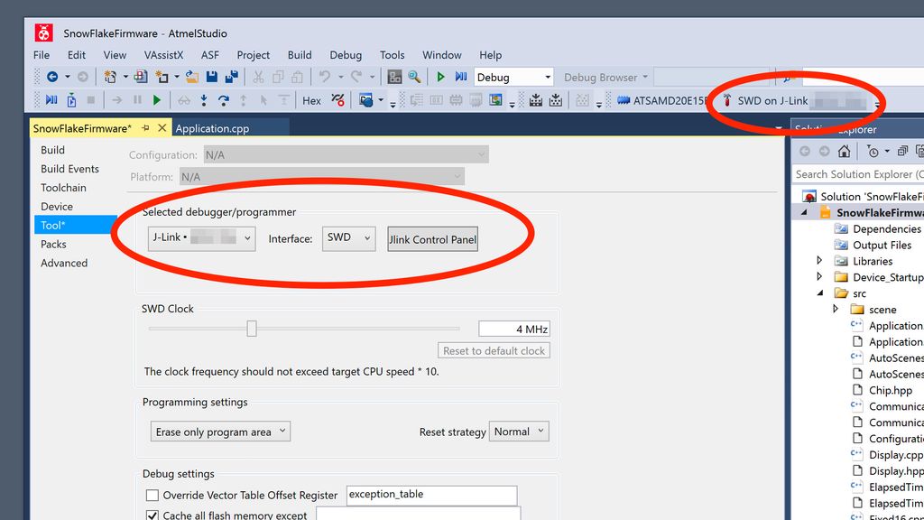
Click on the hammer symbol in the toolbar:
This will open the tool configuration. Select “J-Link” as programmer and “SWD” for the interface.
5. Check the Connection
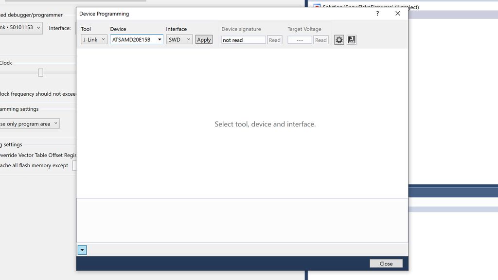
In Atmel Studio, select Device Programming from the “Tools” menu. This will open a new tool for all kinds of manual programming tasks. It is handy to check whether the programmer is working and connected properly, but this is the only place we will use it in this tutorial.
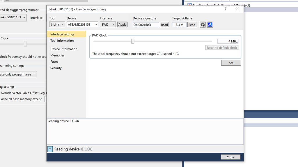
Next, click the Apply button, then the Read button next to the “Device signature” field.
Now you should see “Reading device ID … OK” displayed in the status bar and logging area towards the bottom of the window. If you do, your setup is working properly and you are ready to flash your own firmware.
Compile and Run the Firmware
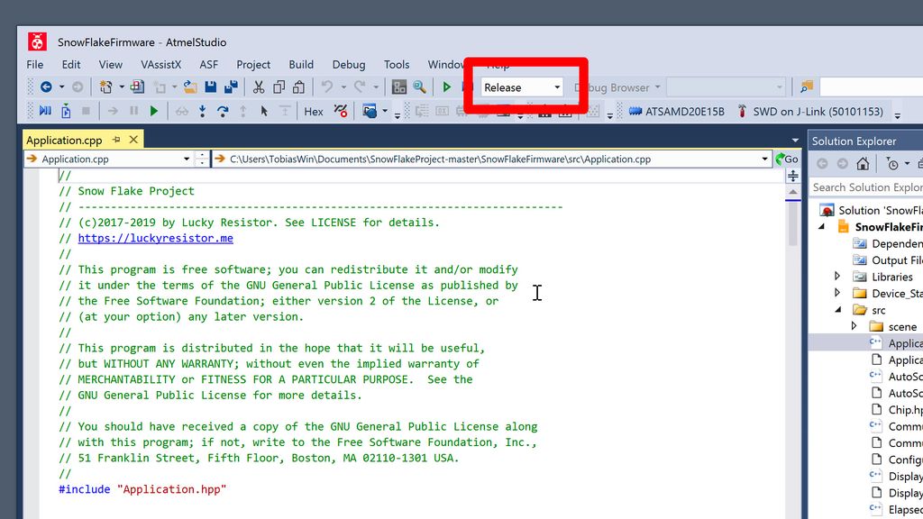
First, make sure you are creating a release build:
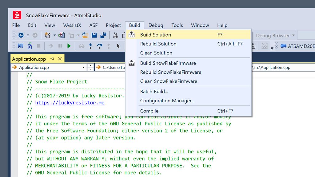
Next, click on Build Solution from the “Build” menu to compile the firmware:
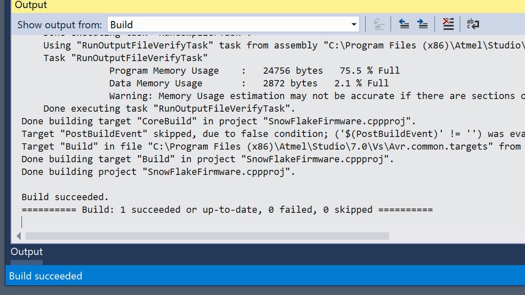
With the latest version of the firmware, you should see “Build: 1 succeeded or up-to-date…” displayed and no error indicators:
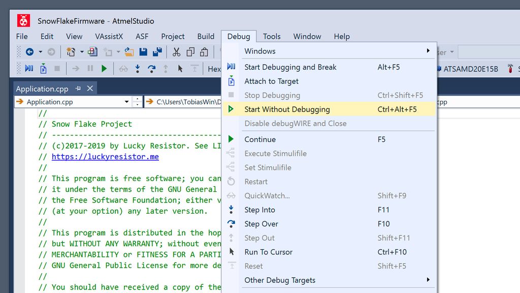
Next, click Start Without Debugging in the “Debug” menu. This writes the firmware to the flash memory and restarts the chip.
That’s all, the attached snowflake is now running the compiled firmware!
Now, don’t forget to write the final firmware to all snowflakes, especially if you changed the patterns or added new ones.
If you reprogram a snowflake in the middle of a strand, reset the entire strand to fix the synchronisation. You can power cycle the strand to accomplish this.
Conclusion
Compiling a custom firmware and writing it into the flash memory of the microcontroller is relatively straightforward. Now you can start adding your own features to the code and experiment with new patterns. In the next article, I will explain how to write custom patterns.
If you have any questions, missed any information, or simply want to provide feedback, feel free to comment below or reach out to us through Twitter!
In Part 6 I walk you through the input panel for my 3D-printed pet feeder: the rotary encoder, LEDs, knob and the example PCB with wiring, filters and level shifting. I include printable files, Gerbers and ordering tips — read the full post for downloads, schematics and testing notes.
I recently tried PCBite, a compact magnetic PCB holder with a mirrored base and adjustable posts. It makes soldering and inspection easier than my old helping-hands. I share close-up photos, usage notes, and where to buy a set—please read on if you’re curious about a simple, solid solution.
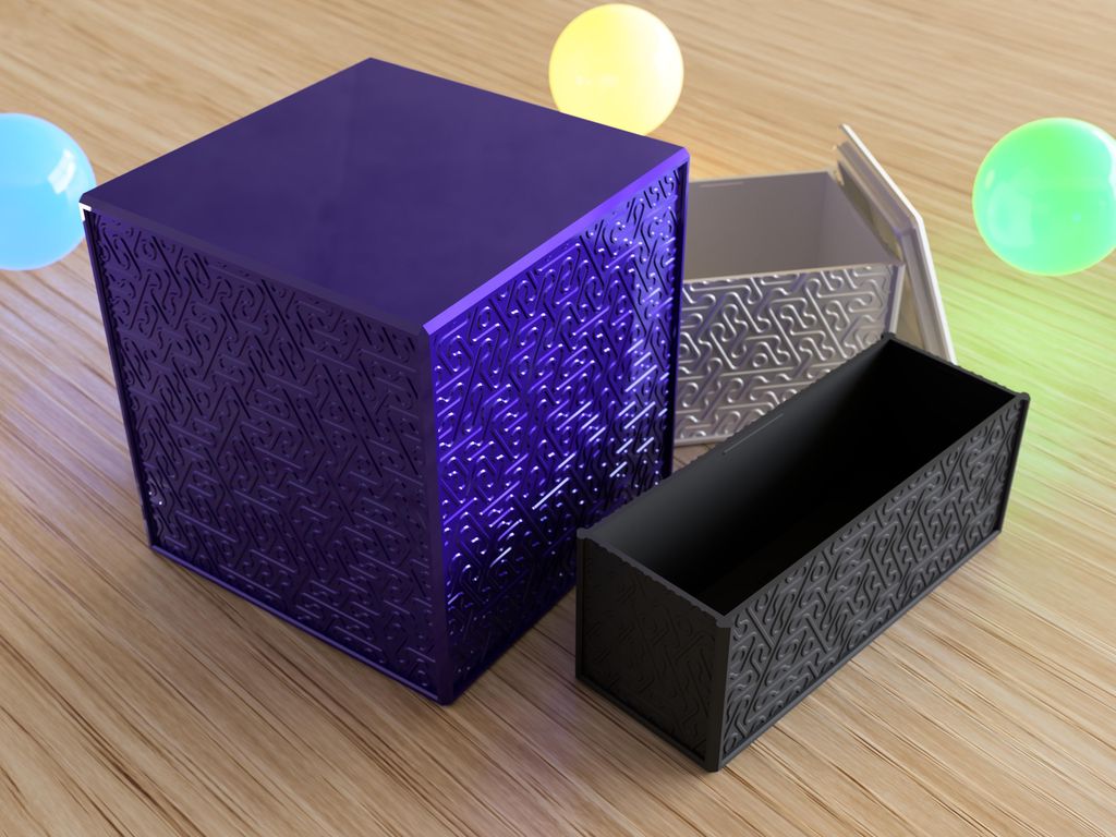
I created a set of 500 printable boxes with a random line pattern—each box unique, sized 35–120 mm with two lid fits per size. I cover part naming, printing tips, and where to download the STLs. If you use 3D printing, please read the full post for files and guidance.
I present a symmetric logic-gate circuit that implements a well-known function. Try to identify the function; hints are provided if you get stuck. If you enjoy this kind of puzzle, read the full post for images, tips, and the solution - I'd love your feedback and suggestions for more puzzles.
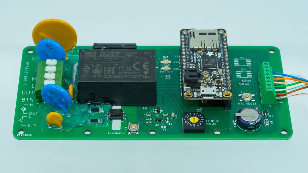
I recently built 'Always-On', a minimal bidirectional mains-to-Feather bridge combining a power sensor and solid-state relay for safe home-control prototypes. I outline design choices, safe firmware testing without mains, and housing tips. If you're exploring a similar controller, read the full post for a practical starting point.
I've been making videos of my LED snowflake decorations, but they still fall short of the live sparkle and diffraction I see. I explain the problems—blinding LED peaks and weak diffraction spikes—and invite you to read the post to watch the clips and see my plan to add digital effects.