published: November 25, 2019 —
last modified: October 23, 2025
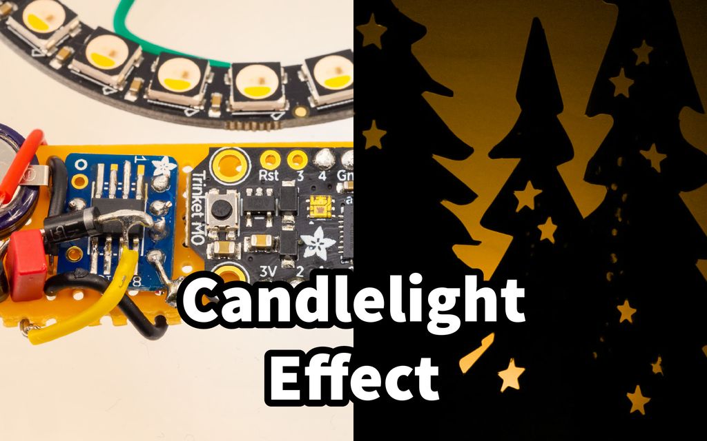
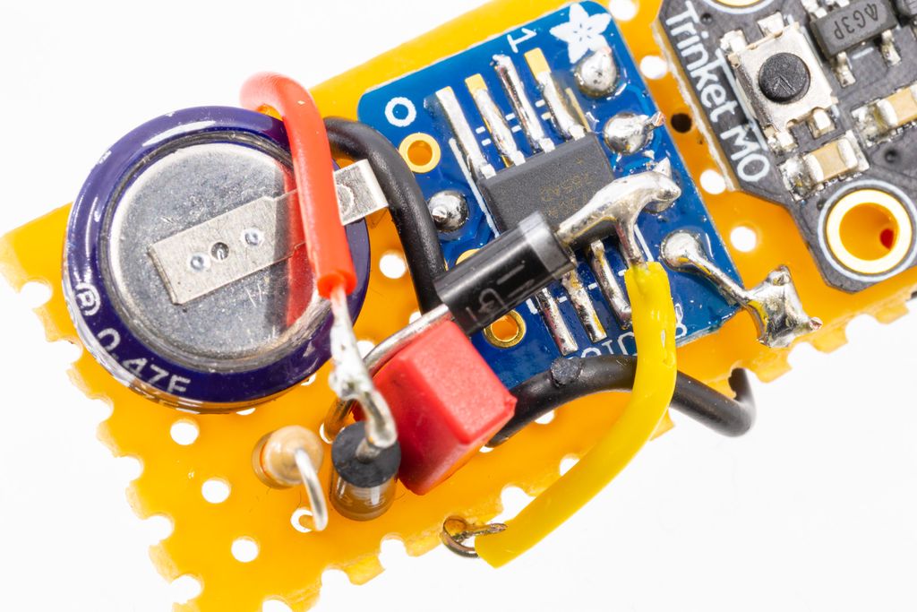
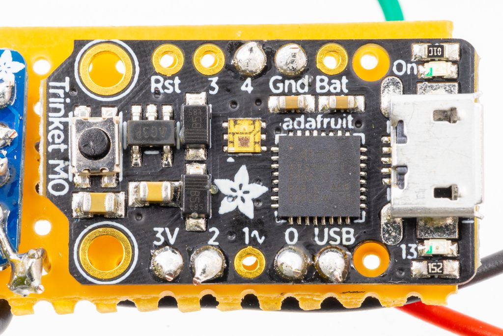
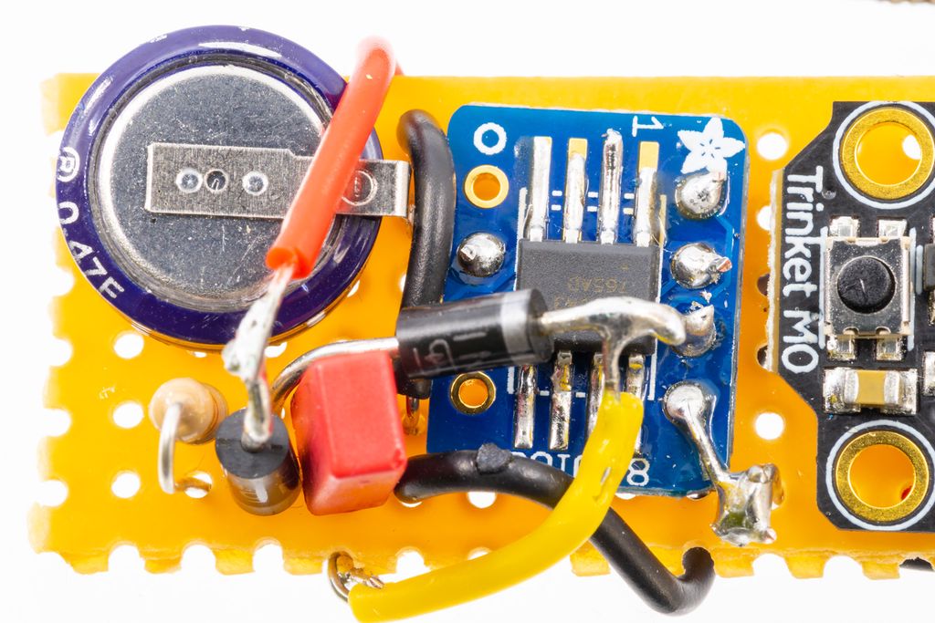
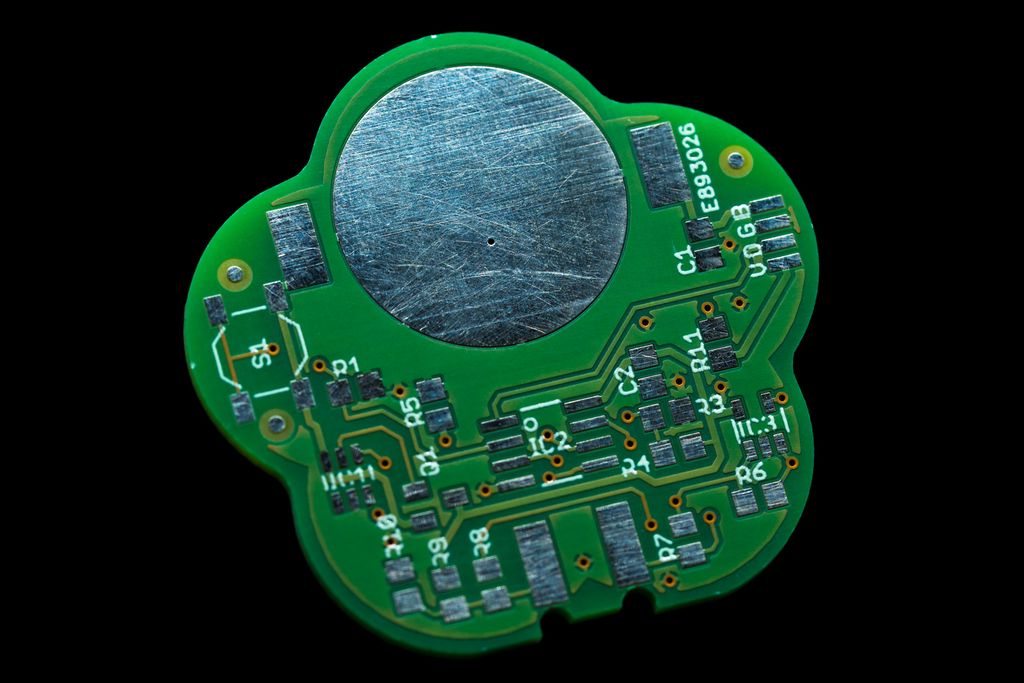
Here I briefly document a very realistic candlelight effect you can build with very few components. It works best if the device is placed in a jar or behind a screen, where the Neopixel ring is not in direct sight.
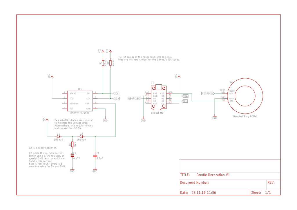
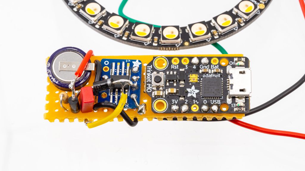
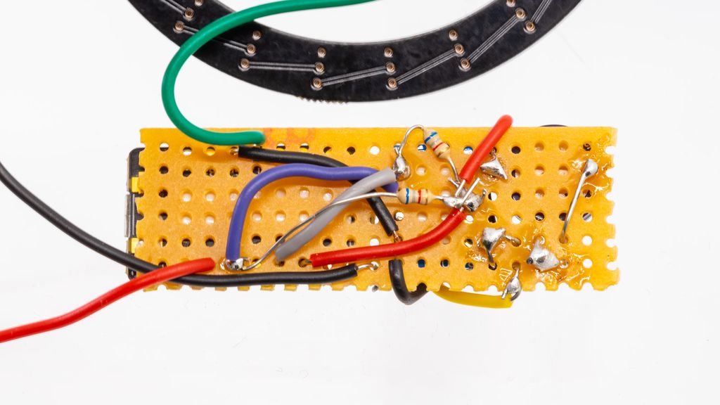
You will find all the required information, schema and the firmware to build the device.
Table of Contents
Features
Realistic candlelight effect.
Real-time clock to automatic turn the decoration on and off at defined hours.
Real-time clock backup power using a supercapacitor.
A USB power bank will run this decoration for weeks.
Video
The following video shows the effect if the device is placed behind a screen:
You need the latest version of the Arduino IDE (Version 1.8.10) and have to install Adafruits SAMD board support. You also need the Adafruit NeoPixel and DotStar library. Install them from the library manager.
Set the Time for the Real-Time Clock
To fix this: uncomment line 201 in the firmware and write the current date and time values into the statement.
// Initialise the RTC driver.
lr::DS3231::initialize();// Uncomment this line and set the current date/time to set the RTC once.
// Make sure to comment it out and re-upload the firmware after setting the RTC!
lr::DS3231::setDateTime(lr::DateTime(2019,11,24,19,11,0));// Check if the RTC is running and had no time issues.
if(!lr::DS3231::isRunning()){
Upload this firmware to set the date and time.
Comment line 201 to disable setting the clock at the start.
Upload the firmware again.
Now, the device should start without any problems, until, for some reason, the RTC has lost the current time. The supercapacitor in the shown configuration will power the clock for one or two weeks without power.
Colour Adjustments
To adjust the colour of the effect, check line 225 of the firmware:
    // Initialise the NeoPixels driver.
    gPixels.begin();
    gPixels.clear();
    gPixels.show();

    // Set the colors for the random effect.
    setRandomBlendColors(Color(0xa048), Color(0x0024));

    // Make the first time check after one second after start.
    gNextTimeCheck = millis() + 1000;
The first argument is the brightest value, the second argument the darkest value. The effect will blend randomly between these. The format for the value is 0xWBGR. Therefore each digit in the 32bit value stands for one colour.
“Air Movement” Adjustments
The speed of the effect is controlled by the delay statement in line 251:
    // If the decoration is enabled, produce a random effect.
    if (gIsEnabled) {
        updateNeoPixels();
        delay(50);
        const uint8_t oldPhase = gRandomPhase;
        gRandomPhase += gRandomSpeed;
        if (oldPhase > gRandomPhase) {
A delay of 20 will give an outdoor effect with some wind, and 50 is more like the effect you have indoors.
Ideas
Add a white paper roll into the Neopixel ring to accentuate the effect.
Use different Neopixel strips with any number of elements.
Add an ambient light sensor, like the VEML7700 to the I2C bus. Now you can turn the decoration as soon as it gets dark. to the I2C bus. Now you can turn the decoration as soon as it gets dark.
To save power:
Add a P-Channel MOSFET in front of the Neopixel ring and just power it if it is in use.
Connect the RTC interrupt to the MCU, so you can put it into sleep mode and wake it using an alarm from the clock.
Add a TPL5111 timer which controls the power for the whole device, which is triggered by the RTC interrupt. This will reduce power while sleeping to the nA range. timer which controls the power for the whole device, which is triggered by the RTC interrupt. This will reduce power while sleeping to the nA range.
Conclusion
I built this small device to replace several smaller electronic candles. It is a small weekend project and a very good start point for similar devices.
If you have questions, missed any information, or simply want to provide feedback, feel free to comment below or reach out to us through Twitter!
I walked through designing and 3D-printing a 70 cm PETG planter for my deep-rooted Ctenanthe. I share the tests, design choices, and practical fixes for warping, filament, split parts, and assembly. If you’re curious about large-scale prints or want the model files and tips, please read the full post.
I built an 8×8 neodymium magnet matrix to keep steel-ball switches in place under a PCB for my Outmoded Sequencer. I walk through marking and drilling 64 holes, gluing each magnet, and sealing with acrylic paint. If you're curious to try this practical approach, read the full post for step-by-step tips.
I’ve published a simple firmware example for the Always-On project, built for PlatformIO and Visual Studio Code with my HAL adapted for Adafruit Feather M0. It explains the hardware mapping, motion-triggered lighting behavior, and timing options. Please read the full post for setup instructions and the GitHub link.
Posted on 2018-08-31— C++, How and Why, Improve your Code
I often encounter poorly written C++ libraries, especially around hardware. In this post I outline four practical strategies—rewrite, refactor, wrap the library, or wrap the interface—to regain control, improve reliability, and reduce pain. Read on for pragmatic steps and examples you can apply to your projects.
I walk you through designing the final PCB for a low-cost plant watering sensor: choosing tools, shaping the board, iterative layouts, BOM decisions, assembly planning and unit-cost calculations. If you want practical steps and cost details, please read the full post to follow the next parts.
I present a symmetric logic-gate circuit that implements a well-known function. Try to identify the function; hints are provided if you get stuck. If you enjoy this kind of puzzle, read the full post for images, tips, and the solution - I'd love your feedback and suggestions for more puzzles.