I created a working firmware example, based on an event loop. In contrast to the minimal example code in my articles, this one contains everything you need to start a project.
Table of Contents
Requirements and Setup
To test and use the code, you need a SAM-D based microcontroller board; For example an Arduino Zero or Adafruit Feather M0. You also need the latest version of the Arduino IDE to compile and upload the code.
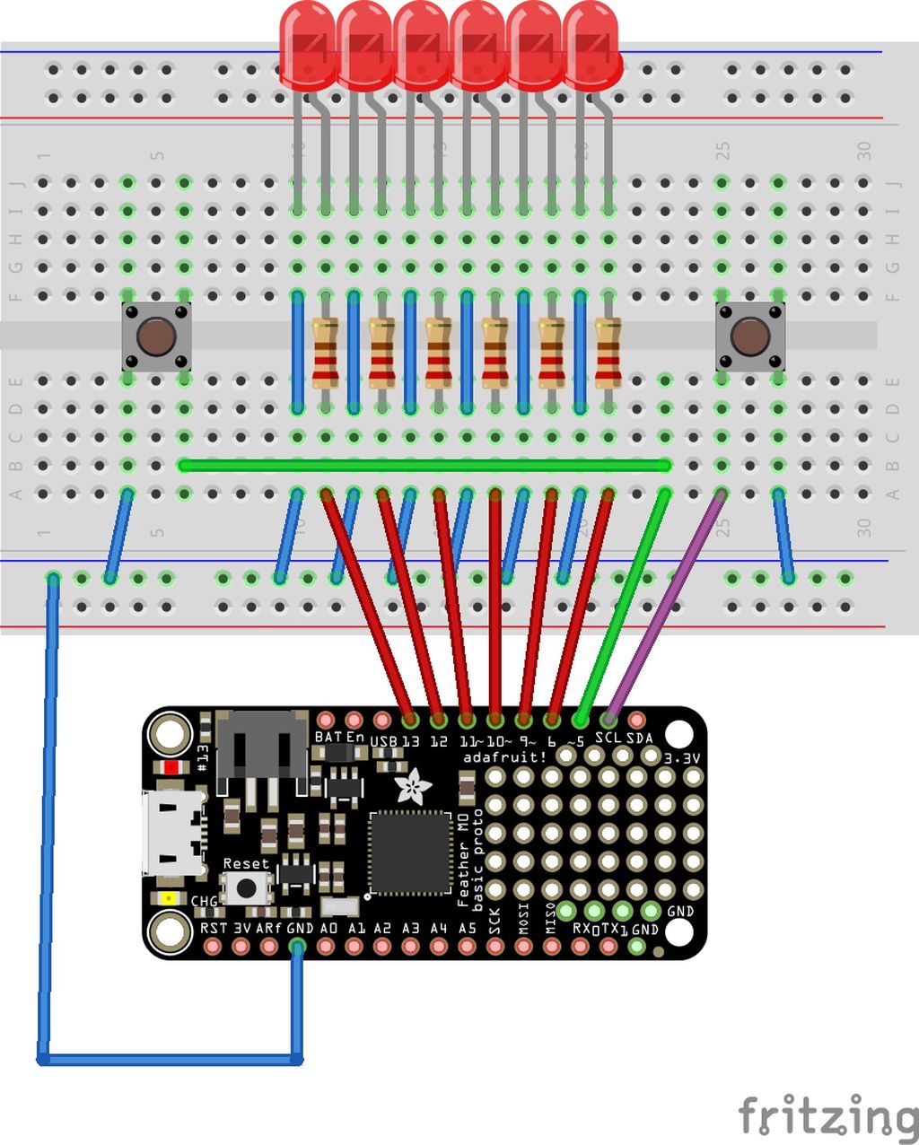
Setup the circuit as shown in the next illustration:
Source Code
Download the source code from the following GitHub repository:
I created a short video demonstrating this simple firmware:
We use two buttons to control the device: a left and a right button. A short press will move the “display” one step to its direction. A long press repeats the command similar to the cursor keys on your keyboard.
Design
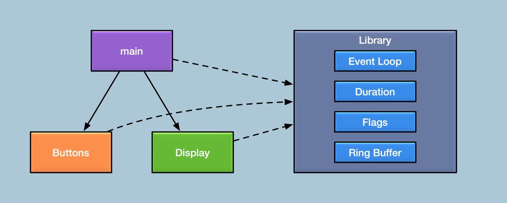
I split the firmware into four parts:
The logic in the main file. in the main file.
The “Buttons” module.
The “Display” module.
A support library in the src subdirectory. subdirectory.
Including the event loop.
Duration definitions.
Flags.
Ring buffer.
I adapted files from my HAL layer for the support library to the Arduino IDE. If you read my posts about C++, you will recognise and understand the functionality provided by the library. In contrast to the examples in my articles, these files contain productive code which is used in real projects.
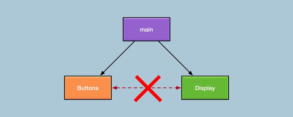
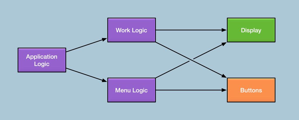
If you study the design illustration, you notice an important fact:
The “Buttons” module doesn’t access the “Display” module and there is no access in the other direction. This is an important design decision to encapsulate the module functionality. It will not only make your code clean and safe but also make it extensible and reusable.
Initialisation
voidsetup(){// Initialise all modules.
Buttons::initialize();Display::initialize();// Register the button press processor.
event::mainLoop().addPollEvent(&processButtonPresses);}
We call the initialize() function from each module in the setup() function. With the last line, we add a polling event to process key presses from the “Button” module.
These initialising functions can also add events to the event system, but these events are not executed until our firmware enters the main event loop. In this firmware, the “Button” module will add a repeated event to poll the button states.
I created this simple high-level display module to control the displayed number by lighting up the corresponding LED. It is simple to replace the implementation without even touching the logic. You can drive a seven-segment display or even an LCD or OLED display — this interface won’t change.
Imagine, you write the firmware for a product which is produced in three different versions:
A cheap version with just a single LED.
A medium-priced version with a seven-segment display.
An expensive version with a built-in OLED display.
With a design like this, you just provide three different implementations of the Display.cpp file, the interface stays the same. You would name these implementations Display_SingleLed.cpp, Display_SevenSegment.cpp and Display_OLED.cpp and include one of these files in the build process.
The example interface is not perfect: The application logic should control the actual number, not the display. Also, it should not be an abstract number. The value requires a clear meaning, like a percentage value or a value with a defined range or unit.
If the value has a clear meaning, the high-level display module can display this value in the best possible way for the attached hardware.
I created this passive interface to access the buttons of the device. There is no function to register a callback for each button press. You have to poll the getNextButtonPress() function for new button presses.
This looks inconvenient for this simple firmware but makes sense if there are multiple modes or states. Imagine, if you press a button, the display shows a menu where you can select items and adjust values. In this case, another part of your firmware can consume the button presses and translate it to menu actions. Using callbacks would make it really hard to maintain a proper encapsulation of the logic.
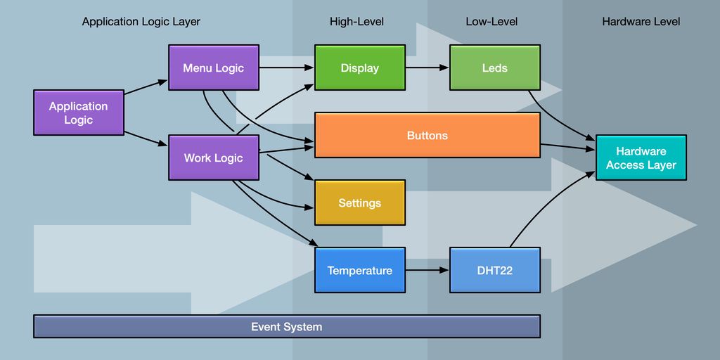
Design if the firmware had a work and menu mode.
Main
I kept the example simple and added the application logic directly to the main file of the project. You should move this logic into an “Application” module with a Application.hpp and Application.cpp file.
This method is added as a polling event, which is called every time the event loop is processed. It retrieves the next button press from the “Buttons” module and in case there is one, translates this into a display change.
The logic is the glue between modules.
Avoid dependencies between modules on the same level. The dependency graph must be clean, pointing from high-level to low-level modules. The logic is the glue between the modules.
Conclusion
Writing event-based firmware is straightforward and result in clean well maintainable code. It supports a strong encapsulation of your modules. With fewer dependencies, it will allow you to reuse the modules for other projects easily.
Do you have any questions, did you miss information, or simply want to provide feedback? Add a comment below or ask a question on Twitter!
I received 3mil polyimide stencils from OSH Stencils for my Swiss precision timer project. They feel flimsy compared to the steel stencils I usually use, but cost much less. I’ll test solder paste application and the first prototype in the coming weeks — please read the full post for results.
I'm not a 3D printing guru, but I built and tested three print-in-place hinges optimized for PETG/ASA and explain the small design choices that make them work reliably. I walk you through bridging, fin widths, overhangs, and conical holes — read the full post to learn how to print them well.
I built a compact Neopixel-based candlelight decoration with a DS3231 RTC and share the schematic, firmware, and build tips here. It's best placed behind a screen or in a jar. Read the full post for parts, assembly photos, and configuration notes to recreate it yourself.
I explain how C++ namespaces prevent name conflicts and why they matter, especially in Arduino projects. I walk through practical patterns—prefixing, selective using-declarations, and importing a namespace—with class and global examples. Read the full post for simple, pragmatic examples to keep your code clearer and conflict-free.
Posted on 2019-07-13— C++, Improve your Code, Learn
I explain why I prefer #pragma once over macro header guards and how it prevents subtle build errors and wasted debugging time. I’ll show examples, common pitfalls, and practical steps to replace guards in existing projects — read on if you want a simple, low-risk improvement.
Posted on 2020-11-21— 3D Printing, Common, Projects
I've been reorganising my lab and designed stackable organiser boxes optimised for fast 3D printing. They use a 60×60mm raster, stabilising walls, dual label slots and rail grids. I offer a free STL subset and explain print settings—read the full post for downloads and the complete shop set.