published: February 23, 2019 —
last modified: October 23, 2025
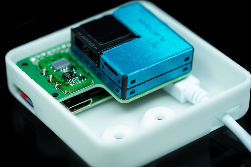
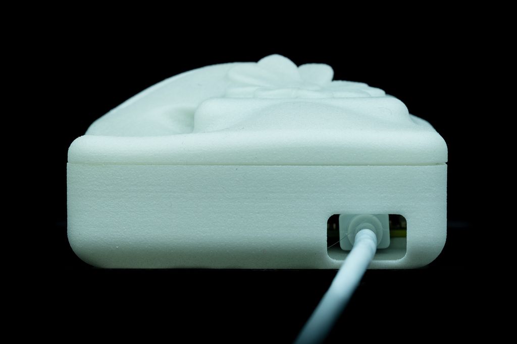
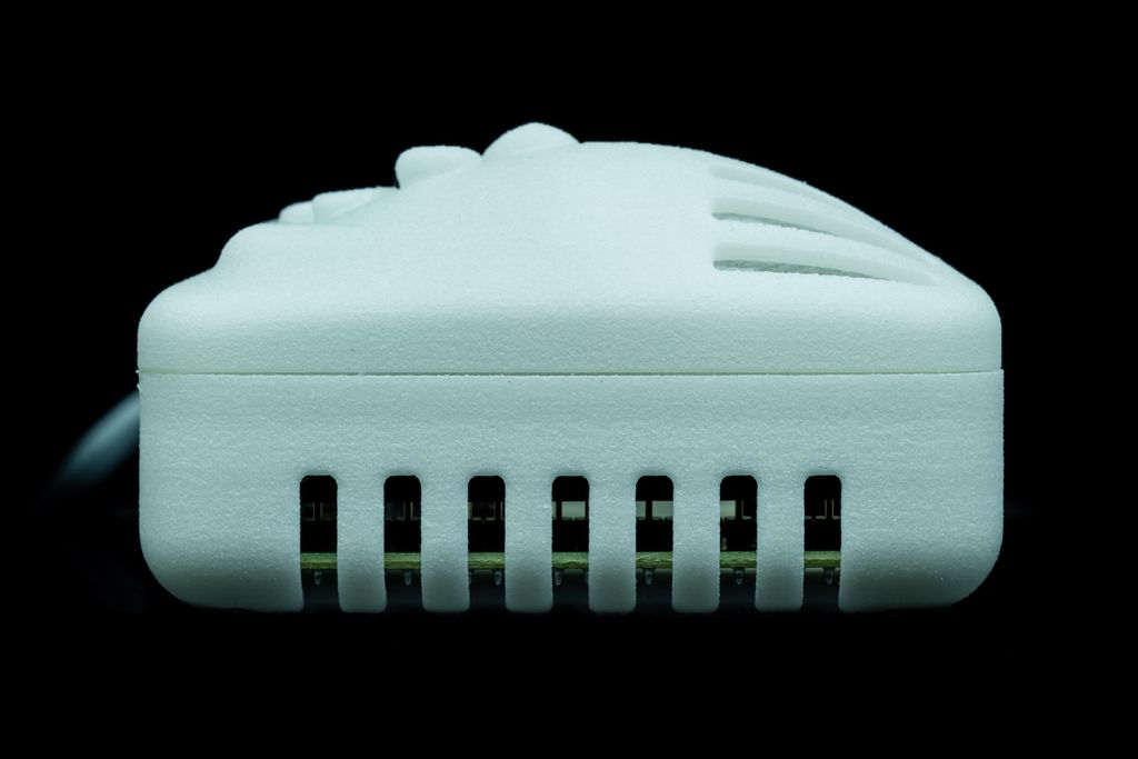
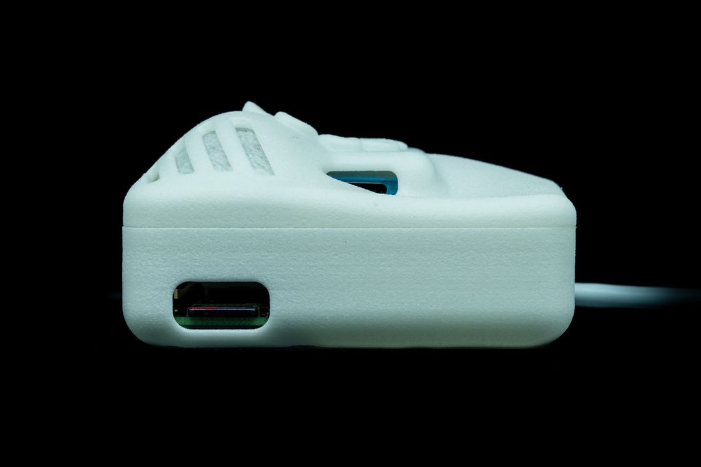
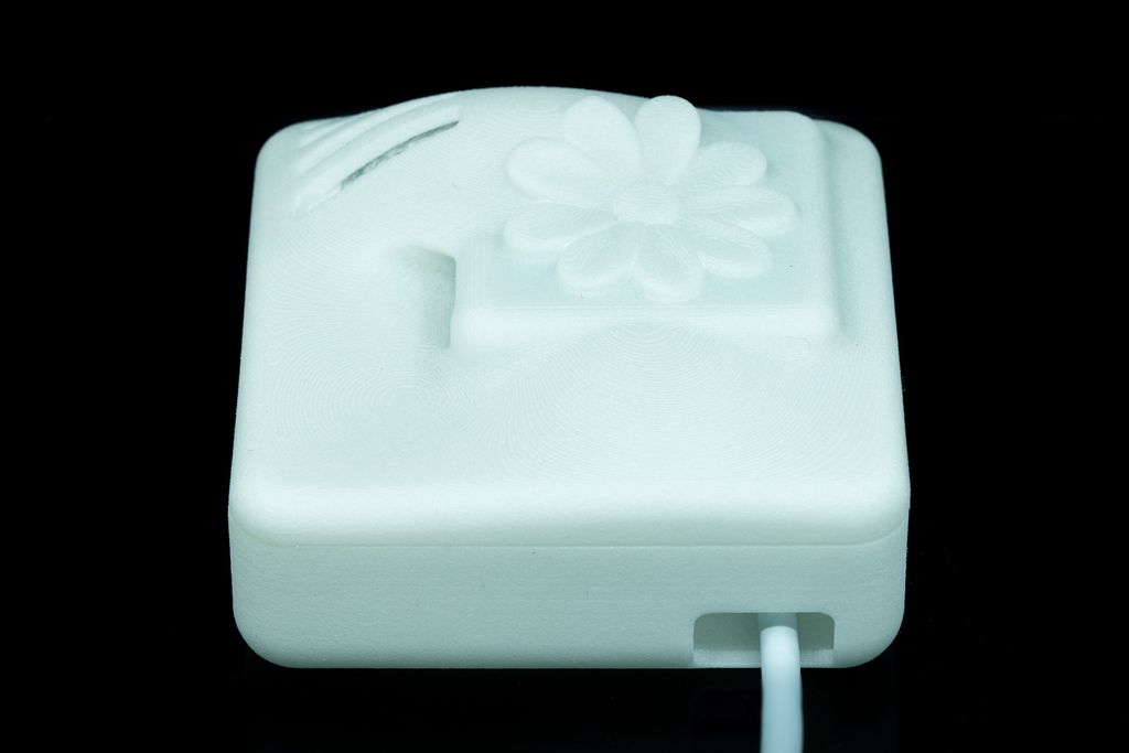
This article is about a small sensor node with a decorative case. It is based on the Raspberry Pi Zero W board with a custom sensor shield.
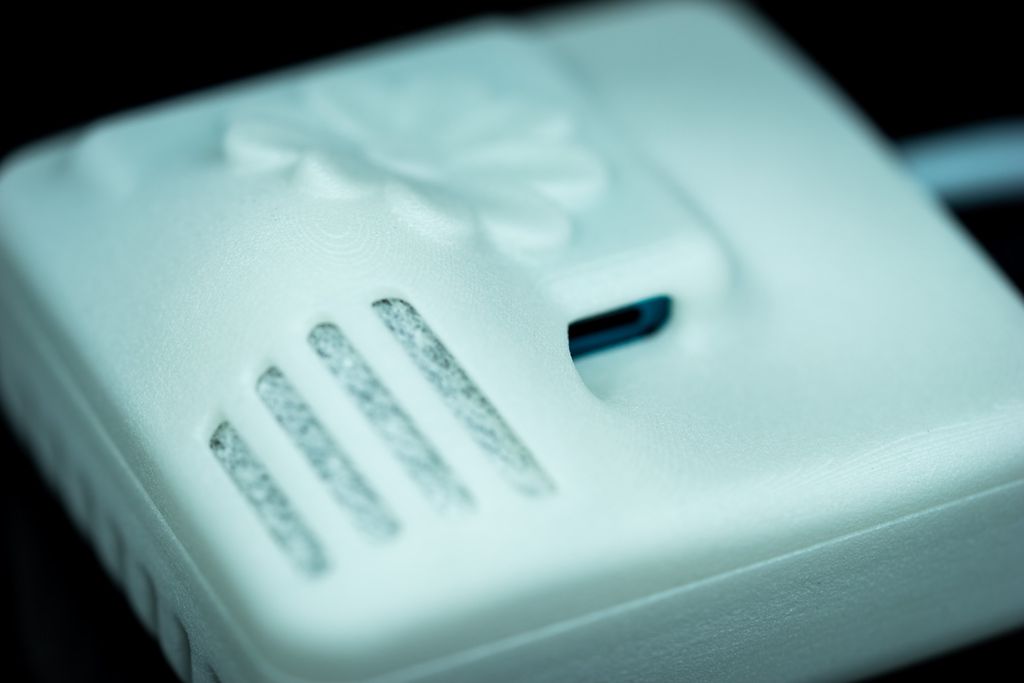
I publish all hardware files for a simple sensor version, so you should be able to build this kind of sensor node and use it to monitor anything you like. You can also extend/modify the design easily with additional sensors. Nevertheless, the case lid design is based around the Plantower PMSA003 particle sensor. It has all the required air vents for this use.
The term “node” is used because the idea of this sensor is to use a large number of these nodes in a network to monitor location and time-based sensor data.
Update 2022-01-07: Added additional images to show the shield assembly in more detail. Fixed the spelling of various sentences.
The Required Hardware
The simplified design is assembled using the following components:
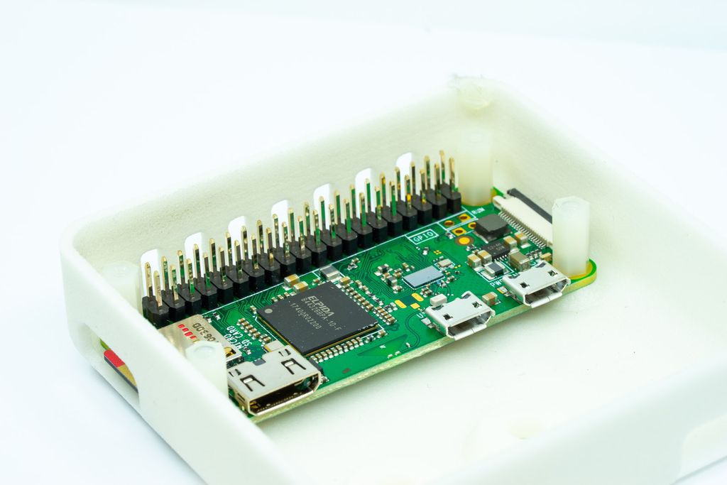
Raspberry Pi Zero W with soldered headers. with soldered headers.
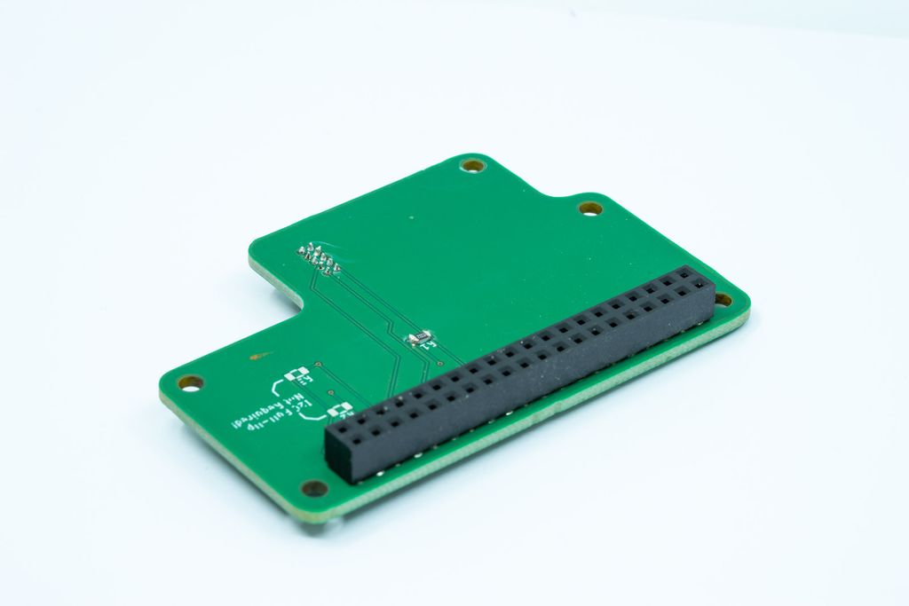
Minimalistic Custom Shield (see description below)
Four short M2.5 screws and nuts to fasten the Raspberry Pi in the case.
Optional four M2.5 10mm long spacer to also fasten the shield.
One or two short M2 screws to fasten the Plantower sensor to the shield.
USB Cable and power supply to power the node.
The Raspberry Pi Zero W
I use the Raspberry Pi Zero W because of its compact size and computing power. Each node can prepare the sensor data, which takes a lot of load from the central processing unit. Also, using a platform like Raspberry Pi easily allows one to run a whole web server on each node - so one can query the sensor data of each node independently. This makes testing a breeze.
The shield works with any variant of Raspberry Pi so that you can use the larger models for testing. Nevertheless, the case is designed to house a Raspberry Pi Zero W and will not work with any other board.
The Shield
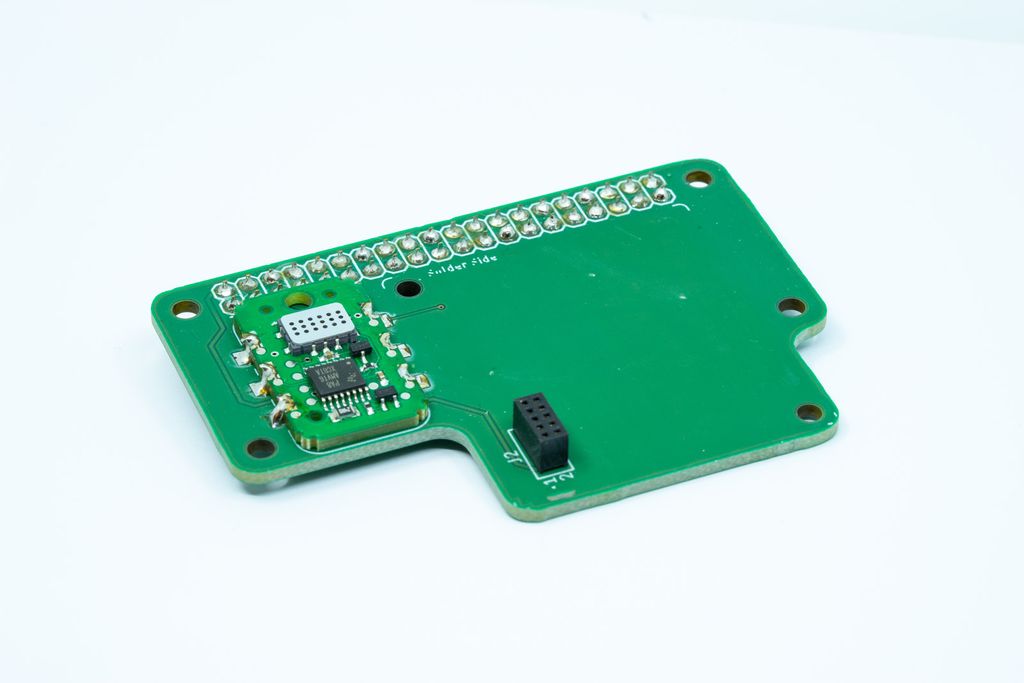
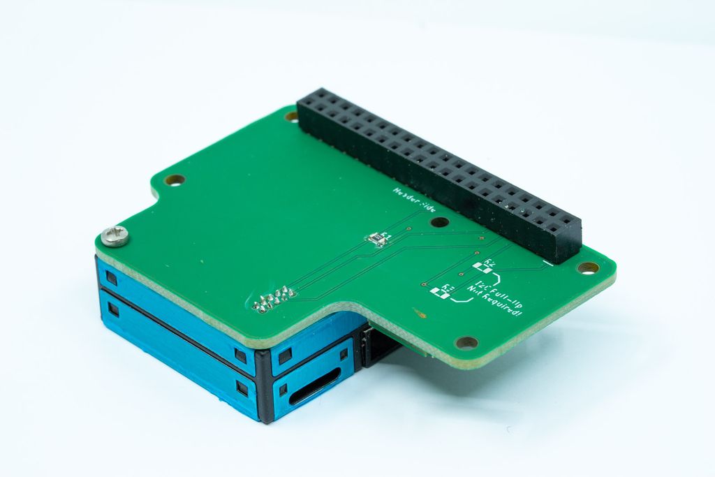
Order the board for the shield from PcbWay.com or OSHPark at a very low price. The shield (“Flower”) I publish here is a very minimalistic version - meant as a good start for your project.
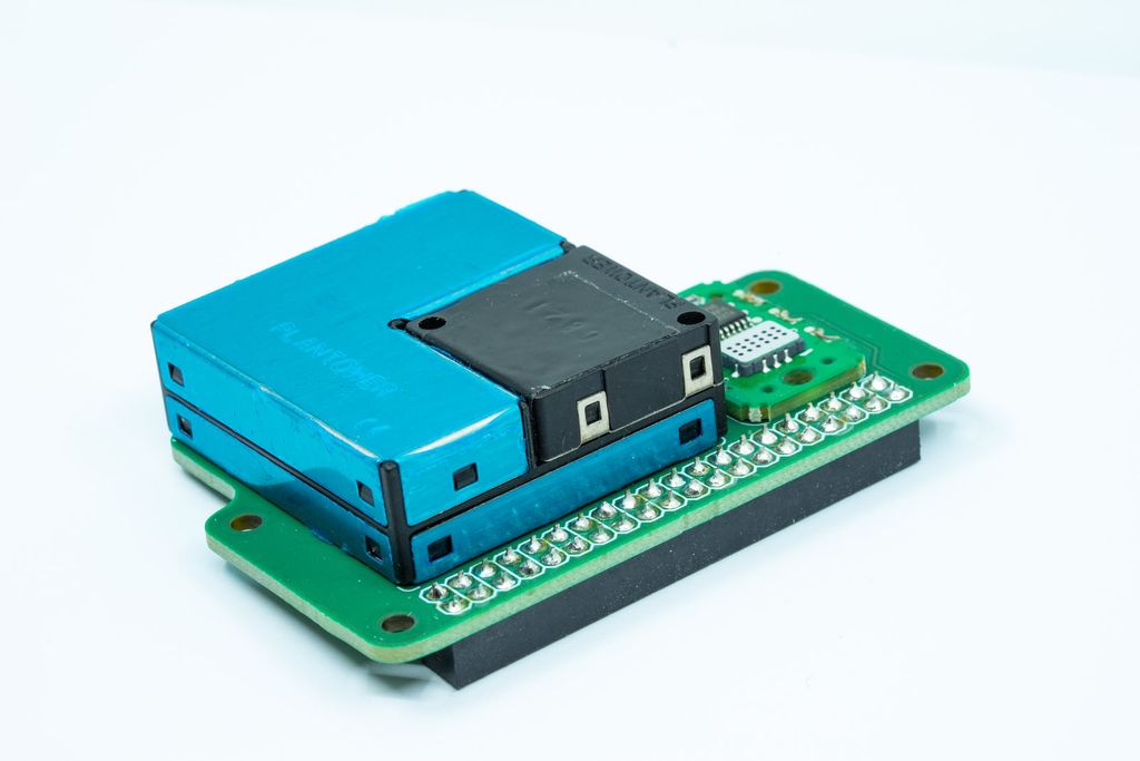
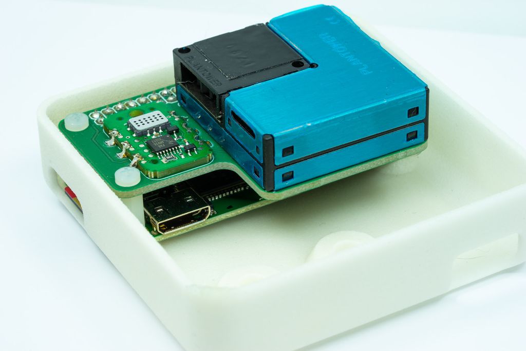
As you can see in the photos, there is enough space for many sensors. The particle sensor will create an airflow in the case so that you can arrange a large number of sensors on a large shield.
Shield Assembly Images
The following images from the shield are based on a prototype. There are small but not functional differences to the provided Gerber files.
Short 40 Pin Header
To attach the shield to the Raspberry Pi, you need a 40 Pin header. You can use the one from Adafruit or buy any header you like. Just make sure you buy a header with a low profile. The maximum height of the header should be 6mm, and 5mm is the optimal height.
This is important for two reasons. First, the distance of the shield to the Raspberry Pi should be 10mm to match the vents in the case. Second, the short header leaves a gap between the shield and the processor board, and this creates a better airflow from the CPU to the air vents on the top.
Plantower PMSA003 Particle Sensor
The Plantower PMSA003 is a tiny laser particle sensor which measures the number of PM1, PM2.5 and PM10 particles in the air. It is no scientifically accurate device, but the sensor comes calibrated, is robust and performs well.
You can get this sensor at a very low price from many Asian suppliers. Make sure you buy one that includes a 10-pin header you can solder to the shield. Otherwise, you need to buy this header separately. One compatible header is the Amphenol 20021311-00010T4LF.
The Optional MICS-VZ-89TE VOC Sensor
For example, I added pads for the Amphenol MICS-VZ-89TE VOC sensor. It is not a cheap sensor, but it can be accessed using I2C and is calibrated. It is also fairly easy to solder.
A little bit cheaper one is the Sensirion SGP30, but it has a 1.8V logic - which requires a level shifter, and it is really hard to hand solder. Alternatively, buy the breakout board from Adafruit and solder it on the shield. In any case, you have to edit the board files.
If you only need a particle sensor, use the unmodified board files and ignore the Sensirion sensor. It does not affect the functionality of the particle sensor.
Screws and Cables
You need four M2.5 screws and four matching nuts to fasten the Raspberry Pi to the case. This will fasten the Raspberry Pi to the case, and the header holds the shield. It is usually enough for most cases.
To make a more stable construction, use four 10mm long M2.5 female-to-female spacers and eight M2.5 screws. Now you can fasten the Raspberry Pi to the case with the spacer and fasten the shield to the spacer from the top. This will give you the best stability.
The Case
The case is made from two separate parts. A generic lower part and the lid.
While the lower part is generic, the upper part (lid) is shaped with vents for the sensors on the shield. This concept aims to add additional sensors for an installed node by just replacing the shield and lid.
The design files I provided with this article do not contain any fastening mechanism to hold the lid to the lower part. Things like this would need the exact knowledge of the used 3D printing method - therefore, they are omitted from these files. Also, the case has 0.1mm between the upper and lower part to make it useable with any printing method.
Just use two small points of hot glue to fasten the two case parts. You can easily separate them later with some force or a little bit of hot air. Or use the design file to add some hooks.
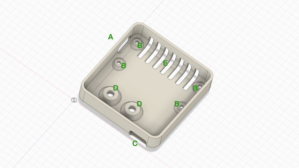
The Lower Part Explained
A - Slot for access to the SD card. - Slot for access to the SD card.
B - Sockets to fasten the Raspberry Pi to the case. - Sockets to fasten the Raspberry Pi to the case.
C - Slot for the USB power cable. - Slot for the USB power cable.
D - Two holes if you like to screw the sensor to a wall. - Two holes if you like to screw the sensor to a wall.
E - Air vents. - Air vents.
Production of the Case
You can produce the case with any 3D printer. All case walls are 2mm thick, so you can print it even using cheap additive methods. For the best decoration results on top, you should choose layers of a maximum of 0.15mm.
Use the following files to print the case as shown:
If you want to change the design, you can use the Fusion 360 file as a base. I had to remove external references from this file. Therefore it is not as parametric as it could be. But you can use it as a good reference if you want to create your lid version.
Enable the SSH server, if this is not already the case.
touch /???/boot/ssh
First Start
Start the node using this SD card and connect.
ssh pi@⟨ip of your node⟩
Secure the Node
Change the password of the user pi
passwd
Use a random >= 32-character password.
Update all packages.
sudo apt update
sudo apt upgrade
sudo rpi-update
Disable the Console on the Serial Line
sudo raspi-config
First, extend the file system.
Disable the console on the serial line.
Make sure the Bluetooth module does not use the serial line:
sudo systemctl disable hciuart
sudo nano /boot/config.txt
Add the following lines:
# Disable BT to allow using the serial line.
dtoverlay=pi3-disable-bt
Add your SSH Public Key
Install your SSH public key for simple access:
mkdir .ssh
chmod 700 .ssh
nano .ssh/authorized_keys
Reboot!
sudo reboot now
Make Sure the Time is Updated
Set up the network to be sure the clock is automatically set using an NTP daemon. This should be the default. Check using:
timedatectl
sudo apt install ntp
sudo nano /etc/ntp.conf
Either use a local NTP server:
Add/uncomment Server ⟨ip of NTP server⟩
Comment out all pool settings.
Or keep the pool settings.
Add the line deny all to prevent any access to the NTP daemon.
Install Required Packages
Next, install the required packages for the python scripts:
sudo apt install python3 python3-serial
Example Software
Reading from the Plantower Sensor
display_pm_values.py
#!/usr/bin/python3"""
Display live sensor values.
"""importconfigparserimporttimeimportserialimportpms_a03fromdatetimeimportdatetimefrompathlibimportPath# Methods# ---------------------------------------------------------------------------defread_value(sensor):"""Read a sensor value and store it in the database."""# Read the value from the sensor.reading=sensor.read()now=datetime.utcnow()print("{}: pm10: {:8d} pm25: {:8d} pm100: {:8d}".format(now.isoformat(),reading.pm10_cf1,reading.pm25_cf1,reading.pm100_cf1))defmain():"""The main method"""# Access the sensor over the serial line.sensor=pms_a03.Sensor("/dev/serial0")# Reading sensor data until terminatedwhileTrue:read_value(sensor)time.sleep(2)if__name__=='__main__':main()# EOF
This code uses the following module, which has to be placed in the same directory. This module is based on the code of the plantower module by Philip Basford. My rewritten version uses a different way to time the sensor reads to reduce the CPU load on the Raspberry Pi. It is still not optimal due to some issues in the serial library.
pms_a03.py
"""
Interface to read from the plantower PMS A003 sensor.
"""importserialimporttime# Constants# ---------------------------------------------------------------------------DEFAULT_SERIAL_PORT="/dev/serial0"DEFAULT_READ_TIMEOUT=2# Classes# ---------------------------------------------------------------------------classSensorReading(object):"""One single reading."""def__init__(self,line):self.pm10_cf1=line[4]*256+line[5]self.pm25_cf1=line[6]*256+line[7]self.pm100_cf1=line[8]*256+line[9]self.pm10_std=line[10]*256+line[11]self.pm25_std=line[12]*256+line[13]self.pm100_std=line[14]*256+line[15]self.gr03um=line[16]*256+line[17]self.gr05um=line[18]*256+line[19]self.gr10um=line[20]*256+line[21]self.gr25um=line[22]*256+line[23]self.gr50um=line[24]*256+line[25]self.gr100um=line[26]*256+line[27]classSensorException(Exception):"""Exception if no data can be read."""passclassSensor(object):"""The interface class."""def__init__(self,port=DEFAULT_SERIAL_PORT,read_timeout=DEFAULT_READ_TIMEOUT):self.port=portself.read_timeout=read_timeouttry:self.serial=serial.Serial(port=self.port,baudrate=9600,timeout=1)exceptserial.SerialExceptionase:raiseSensorException(str(e))def_verify(self,recv):"""Verify the checksum of the data."""calc=0ord_arr=[]forcinbytearray(recv[:-2]):calc+=cord_arr.append(c)sent=(recv[-2]<<8)|recv[-1]ifsent!=calc:raiseSensorException("Checksum invalid")defread(self):"""Read a new value from the sensor."""recv=b''timeout_time=time.monotonic()+self.read_timeoutself.serial.reset_input_buffer()whileTrue:inp=self.serial.read(1)ifinp=='':time.sleep(0.1)continueifinp==b'\x42':recv+=inpinp=self.serial.read(1)ifinp==b'\x4d':recv+=inprecv+=self.serial.read(30)breakiftime.monotonic()>timeout_time:raiseSensorException("No message recieved")self._verify(recv)returnSensorReading(recv)
Reading from the VOC Sensor
Reading from the VOC sensor is not very simple to do using Python. Here is a small C++ command to read the current values from the Sensor and print them as JSON data.
Call this small command from your python code to get the current values from the sensor.
read_mics_vz_89te.cpp
//
// Read the current values from the MiCS VZ 89TE sensor.
// ---------------------------------------------------------------------------
// (c)2019 by Lucky Resistor. See LICENSE for details.
//
// This program is free software; you can redistribute it and/or modify
// it under the terms of the GNU General Public License as published by
// the Free Software Foundation; either version 2 of the License, or
// (at your option) any later version.
//
// This program is distributed in the hope that it will be useful,
// but WITHOUT ANY WARRANTY; without even the implied warranty of
// MERCHANTABILITY or FITNESS FOR A PARTICULAR PURPOSE. See the
// GNU General Public License for more details.
//
// You should have received a copy of the GNU General Public License along
// with this program; if not, write to the Free Software Foundation, Inc.,
// 51 Franklin Street, Fifth Floor, Boston, MA 02110-1301 USA.
//
#include<unistd.h>#include<fcntl.h>#include<sys/ioctl.h>#include<linux/i2c-dev.h>#include<chrono>#include<thread>#include<cstdint>#include<iostream>// This code is required, because this sensor has a little bit special
// protocol to access the values.
/// The I2C address of the chip.
///
constuint8_tcChipAddress=0x70;/// The device to use.
///
conststd::stringcDevicePath="/dev/i2c-1";/// The delay to wait before the result is read from the sensor.
///
conststd::chrono::millisecondscReadDelay(300);/// The command.
///
enumclassCommand:uint8_t{SetPPMCO2=0b000001000,GetStatus=0b000001100,GetRevision=0b000001101,GetR0=0b000010000};/// The file pointer to the I2C device.
///
inti2c_fd=0;/// If the command shall display verbose messages.
///
boolisVerbose=false;/// Open the I2C device.
///
/// @return `true` on success.
///
boolopenBus(){if(isVerbose){std::cout<<"# Open the bus."<<std::endl;}i2c_fd=open(cDevicePath.c_str(),O_RDWR);if(i2c_fd<0){std::cerr<<"Failed to open the I2C bus device. Path: "<<cDevicePath<<std::endl;returnfalse;}if(ioctl(i2c_fd,I2C_SLAVE,cChipAddress)<0){std::cerr<<"Failed to configure the I2C bus device. Error: "<<errno<<std::endl;returnfalse;}returntrue;}/// Close the I2C device.
///
/// @return `true` on success.
///
boolcloseBus(){if(isVerbose){std::cout<<"# Close the bus."<<std::endl;}close(i2c_fd);returntrue;}/// Write data to the I2C bus.
///
/// @param data The data to write.
/// @param size The size of the data to write.
/// @return `true` on success.
///
boolwriteData(constuint8_t*data,intsize){if(write(i2c_fd,data,size)!=size){std::cerr<<"Failed to write to the bus. Error: "<<errno<<std::endl;returnfalse;}returntrue;}/// Read data from the I2C bus.
///
/// @param data The buffer to read data into it.
/// @param size The number of bytes to read.
/// @return `true` on success.
///
boolreadData(uint8_t*data,intsize){if(read(i2c_fd,data,size)!=size){std::cerr<<"Failed to read from the bus. Error: "<<errno<<std::endl;returnfalse;}returntrue;}/// Calculate the checksum for a command.
///
/// @param buffer The buffer to use for calculation.
/// @param size The size of the buffer.
/// @return The calculated checksum.
///
uint8_tgetCRC(constuint8_t*buffer,constuint8_tsize){uint16_tsum=0;for(uint8_ti=0;i<size;i++){sum+=buffer[i];}uint8_tcrc=static_cast<uint8_t>(sum);crc+=(sum/0x0100);crc=(0xff-crc);returncrc;}/// Write a command to the bus.
///
/// @param cmd The command to send.
/// @param data The data to attach to the command.
/// @return `true` on succes.
///
boolwriteCommand(constCommandcmd,constuint32_tdata=0){uint8_tbuffer[6];buffer[0]=static_cast<uint8_t>(cmd);buffer[1]=static_cast<uint8_t>(data&0x000000ffUL);buffer[2]=static_cast<uint8_t>((data&0x0000ff00UL)>>8);buffer[3]=static_cast<uint8_t>((data&0x00ff0000UL)>>16);buffer[4]=static_cast<uint8_t>((data&0xff000000UL)>>24);buffer[5]=getCRC(buffer,5);constautoresult=writeData(buffer,6);if(!result){std::cerr<<"Failed to send a command to the bus."<<std::endl;}returnresult;}/// Read a result from the bus.
///
/// @param data The data to read.
/// @return `true` on success.
///
boolreadResult(uint8_tdata[7]){if(!readData(data,7)){returnfalse;}constuint8_tcrc=getCRC(data,6);if(data[6]!=crc){std::cerr<<"The checksum of the received result is not valid."<<std::endl;returnfalse;}returntrue;}/// Get the current values from the sensor.
///
/// @param[out] voc The voc value.
/// @param[out] co2 The co2 value.
/// @return `true` on success.
///
boolgetValues(float&voc,float&co2){if(isVerbose){std::cout<<"# Reading the current values."<<std::endl;}// Repeat the read three times if necessary.
for(uint8_tcomTry=0;comTry<3;++comTry){if(writeCommand(Command::GetStatus)){std::this_thread::sleep_for(cReadDelay);uint8_tdata[7];if(readResult(data)){if(isVerbose){constuint32_trawValue=(static_cast<uint32_t>(data[2])<<16)|(static_cast<uint32_t>(data[3])<<8)|static_cast<uint32_t>(data[2]);std::cout<<"# Raw data values: voc="<<static_cast<uint32_t>(data[0])<<" co2="<<static_cast<uint32_t>(data[1])<<" raw="<<rawValue<<std::endl;}//voc = static_cast<float>(static_cast<int16_t>(data[0]-13)) * static_cast<float>(1000.0f/229.0f);
//co2 = (static_cast<float>(static_cast<int16_t>(data[1]-13)) * static_cast<float>(1600.0f/229.0f)) + static_cast<float>(400.0f);
// Formula supplied by the manufacturer:
voc=((data[0]-13)*(1000/229));co2=((data[1]-13)*(1600/229)+400);returntrue;}std::this_thread::sleep_for(std::chrono::milliseconds(20));}}std::cerr<<"Failed to read the values from the sensor."<<std::endl;returnfalse;}/// Parse the command line parameters.
///
boolparseCommandLine(intargc,char*argv[]){for(inti=0;i<argc;++i){constautoarg=std::string(argv[i]);if(arg=="-h"||arg=="--help"){std::cerr<<"Usage: read_mics_vz_89te [-h][-v]"<<std::endl;std::cerr<<" -h|--help Display this help."<<std::endl;std::cerr<<" -v Show verbose messages."<<std::endl;returnfalse;}elseif(arg=="-v"){isVerbose=true;}}returntrue;}intmain(intargc,char*argv[]){// Initialize and open the bus.
if(isVerbose){std::cout<<"# Success."<<std::endl;}if(!parseCommandLine(argc,argv)){return1;}if(!openBus()){return1;}floatvoc=0.0f;floatco2=0.0f;if(!getValues(voc,co2)){return1;}// Output the values as JSON
std::cout<<"{ \"voc\": "<<voc<<", \"co2\": "<<co2<<" }"<<std::endl;// Close the bus.
closeBus();// Success
if(isVerbose){std::cout<<"# Success."<<std::endl;}return0;}
Posted on 2019-08-05— C++, Improve your Code, Learn
I provide a complete event-loop firmware example for SAM‑D boards (Arduino Zero, Feather M0). I explain module design—Buttons, Display, and a support library—initialisation and polling logic, and link the source and demo. If you're curious, read the full post for code and implementation notes.
I photographed common SMD components through a microscope to reveal how small imperfections appear up close. I cropped each image for clarity and included a 1 mm scale and captions describing the parts. If you’re curious about what resistors, capacitors and tiny ICs look like under magnification, read on.
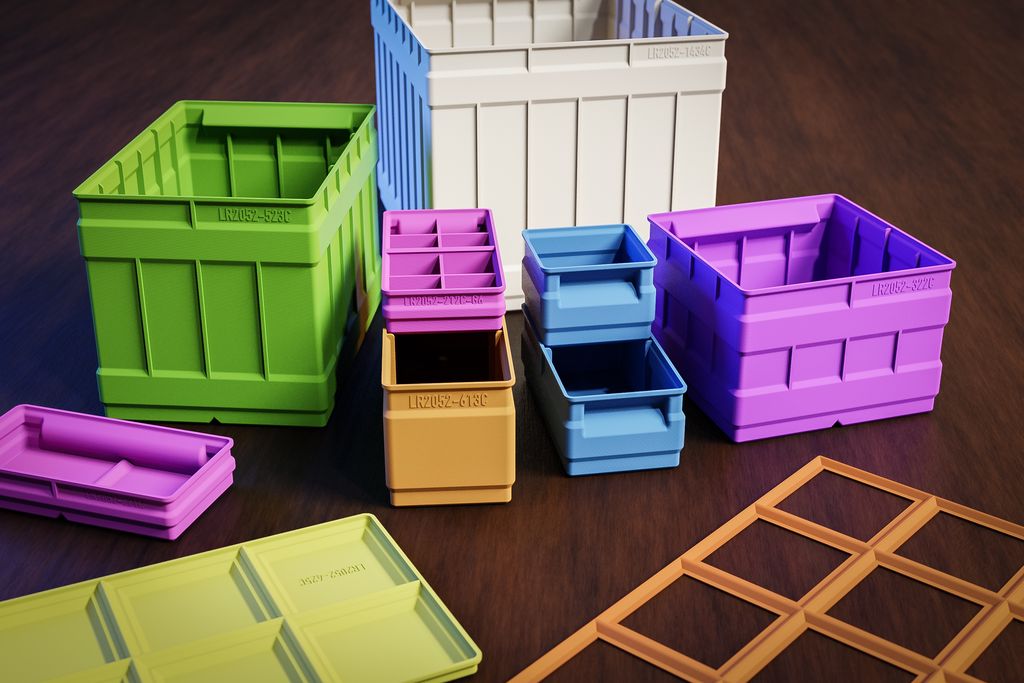
I’ve released a major update to my 3D-print storage box system: expanded sizes (up to 6x6 and 9x9 split), improved geometries, 3MF files, JPEG previews, and more dividers. If you use my boxes or print them yourself, read the full post for download links, compatibility notes, and printing tips.
I explain how C++ namespaces prevent name conflicts and why they matter, especially in Arduino projects. I walk through practical patterns—prefixing, selective using-declarations, and importing a namespace—with class and global examples. Read the full post for simple, pragmatic examples to keep your code clearer and conflict-free.
Posted on 2019-07-14— C++, Improve your Code, Learn
I wrote a concise guide for embedded developers to refactor Arduino/C++ firmware into clean, modular components. I walk you through creating Display, Buttons, and Animation modules, testing and committing small changes, and improving maintainability. If you'd like practical steps and examples, please read the full article.
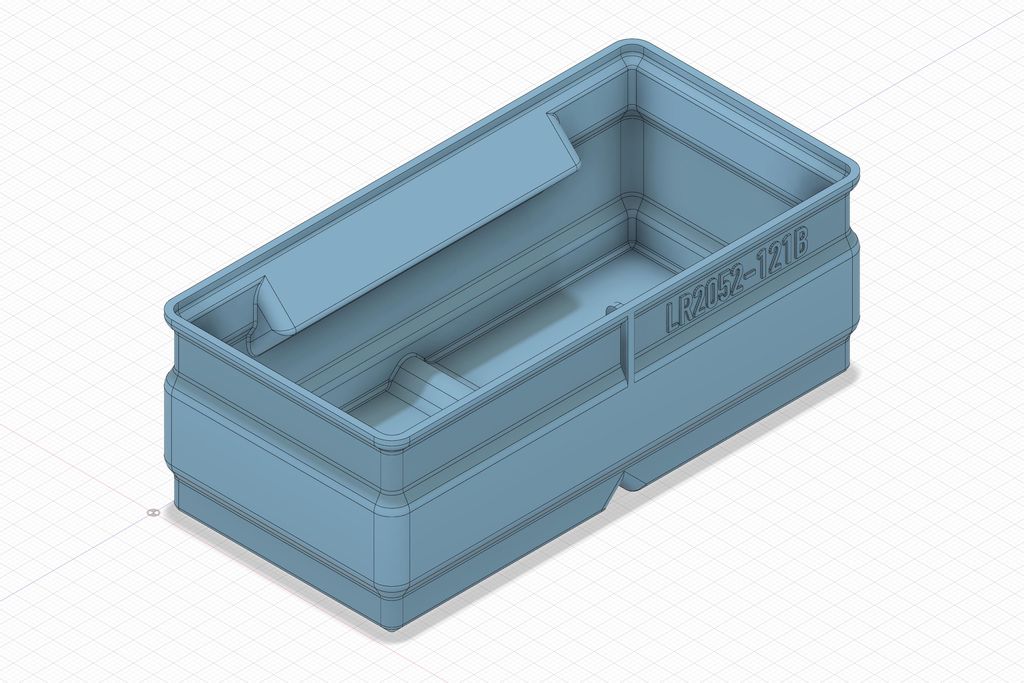
I've released several new 3D-print storage boxes with the label area moved to a different side so identical boxes can sit in a drawer with labels aligned. I explain size variants, rib adjustments, and how to download updated files. Please read the full post to see illustrations and the catalog link.