published: March 17, 2018 —
last modified: October 23, 2025
For my current project I searched for a good boost power converter which is able to deliver continuous 400mA power for various sensors.
There are an endless number of good boost converters around, but not many can be hand soldered to a board. I would really like to see some like the TPS61092 with SOIC or similar packages. The biggest problem seems to be the heat transport, why most chips have to be mounted flat on the board.
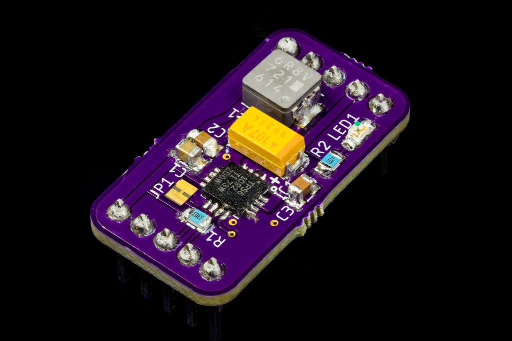
Before using the chip in my project, I created a small test board. Using this board I can test various things. First I liked to test the performance under load. Next I tested if the chip can be hand soldered and finally I tested the final board layout I will use in my project.
Performance
The performance of this chip is really good, producing a very stable output. I designed everything for a load up to 2A with all suggested components from the specification. There will never be a higher load than 0.5A, so I probably could use a smaller coil for the final project.
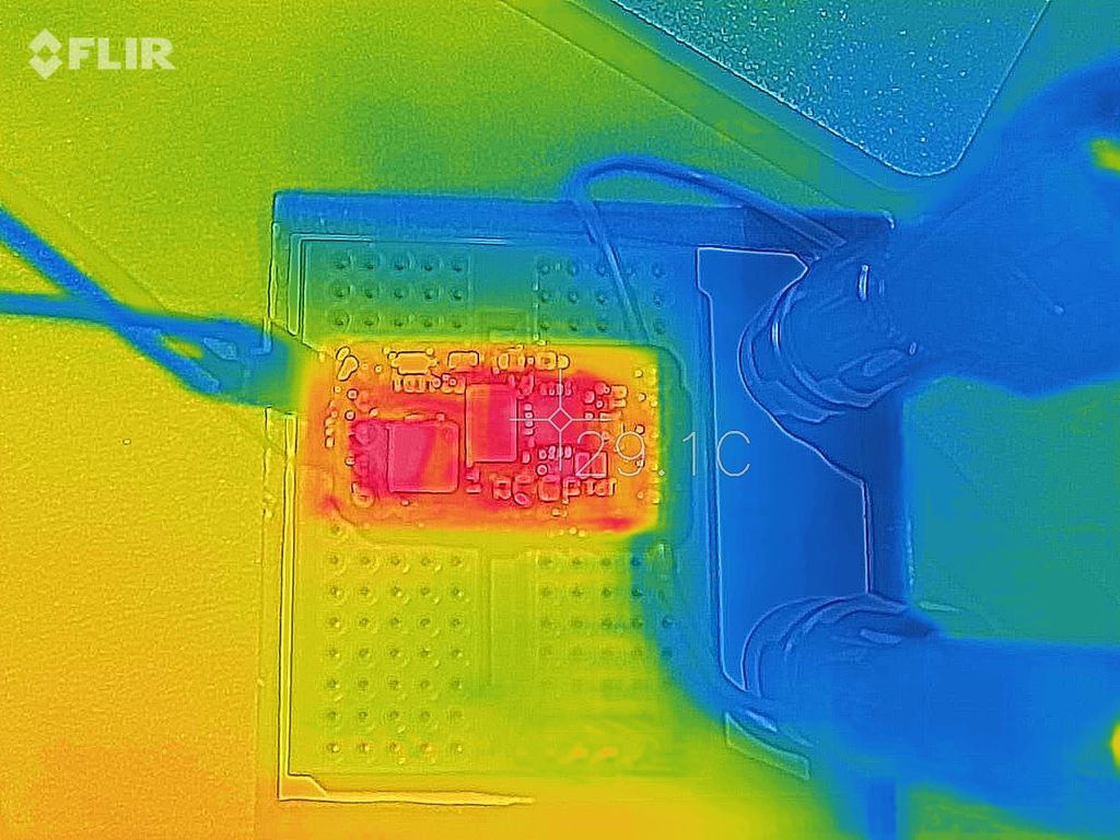
Running under 0.5A load from 3.3V for over half an hour, the chip stays quite cold. Even in my case, where the chip bottom is not directly soldered to the board, it seems to be able to transfer the heat into the board. This is nicely visible in the thermal image of the board.
The Board
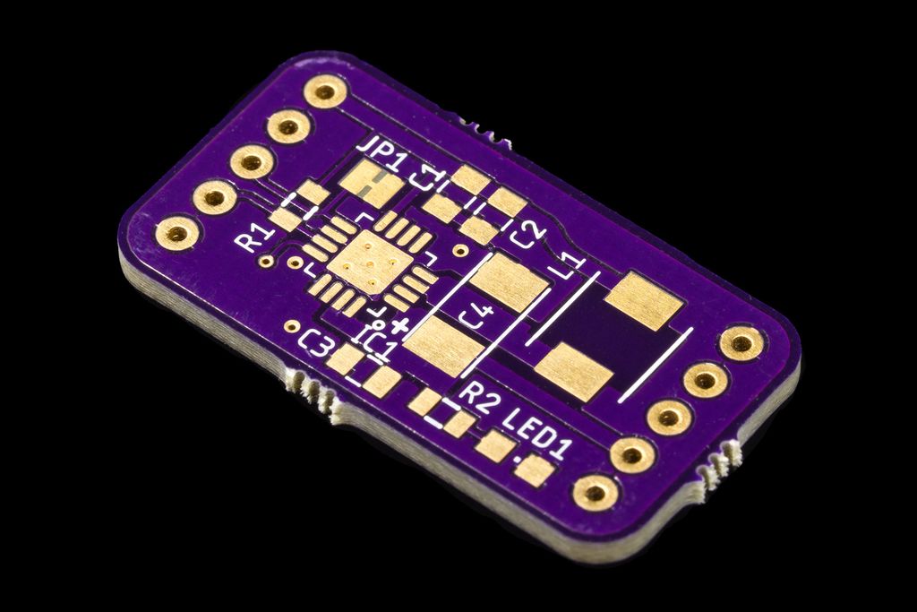
The board was produced by OSH Park in a good quality. If you like to experiment with this chip, you can order this board very cheap at OSH Park using the following link.
You can find the BOM for this board here. The resistor R2 and LED1 are optional, all other components are required for the power converter to work.
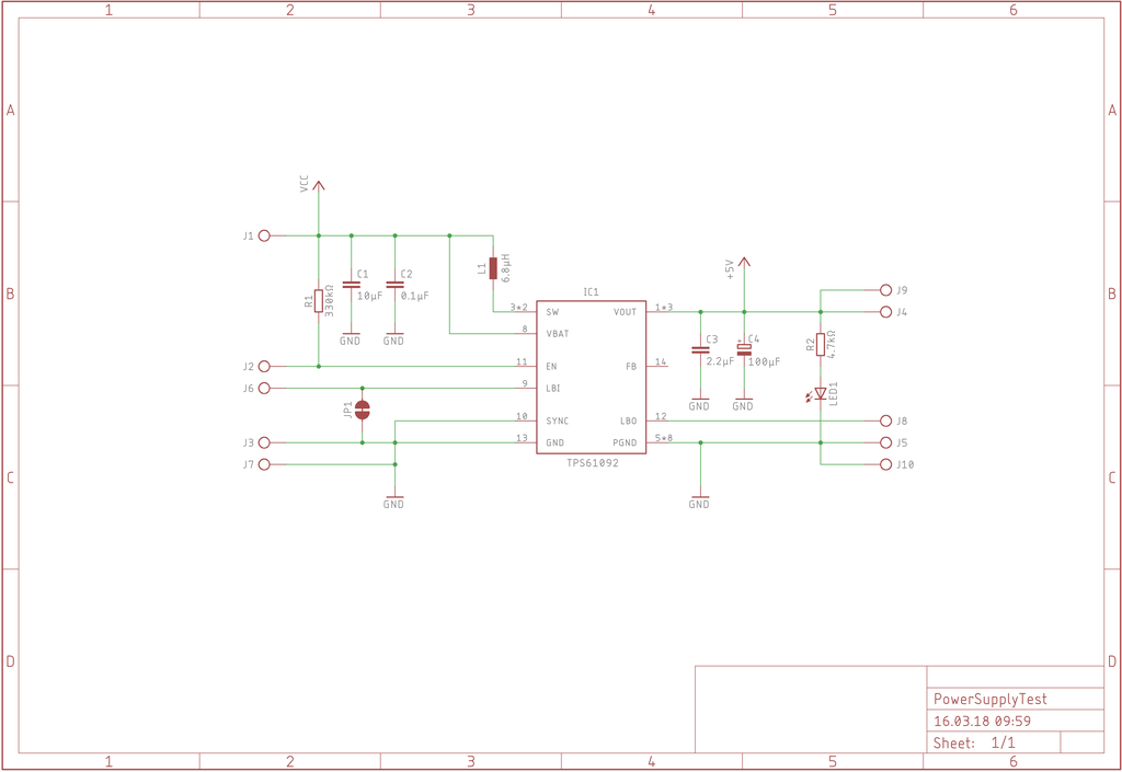
I routed all pins of the board to the connectors, so you can also test the battery level detection of the chip if you like. The image below shows the schema for this very simple board:
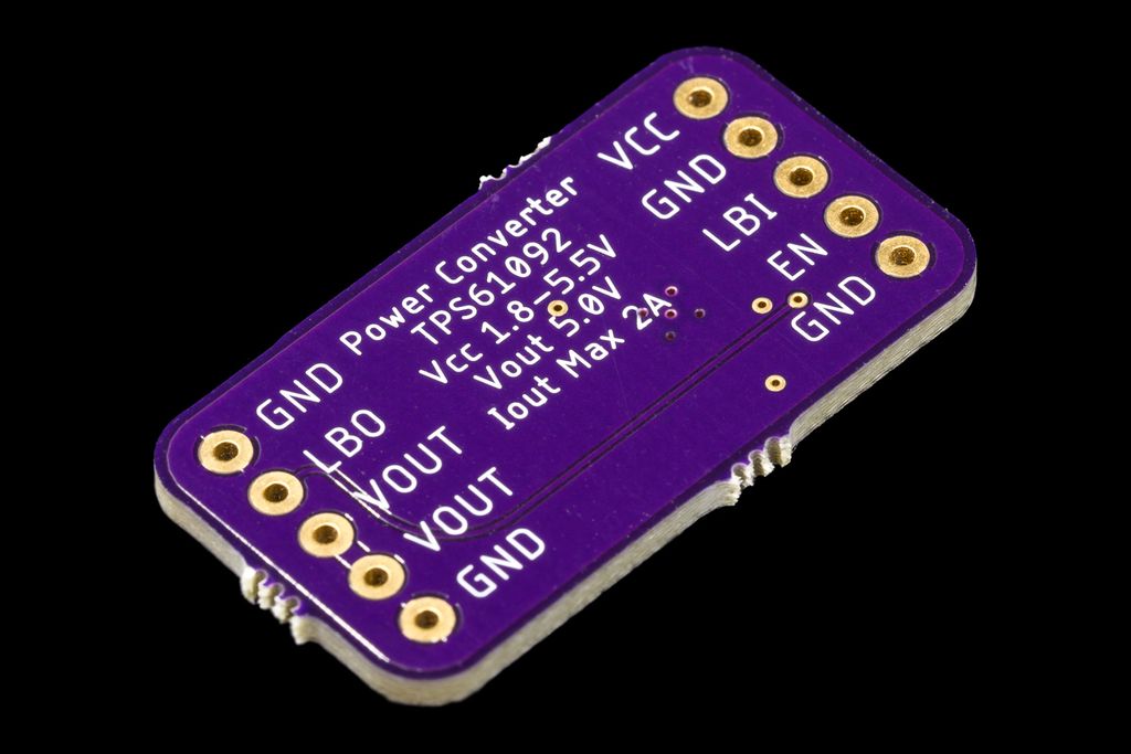
The schema lacks the correct labels for the connectors, see the silkscreen on the bottom of the board to see the meanings of the connectors.
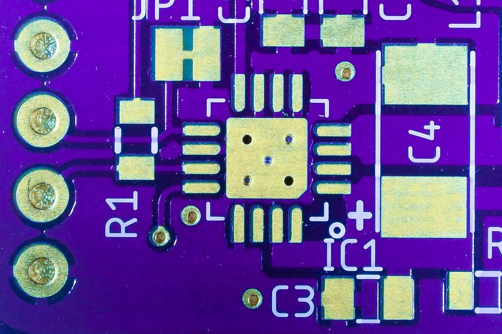
The board looks great, especially the silk screen is incredible precise. All these labels are only 1mm in height. There is just a small misalignment between the copper layer and the solder mask (<0.05mm).
Soldering
Hand soldering this chip is no pleasant experience, nevertheless it is feasible. I designed the board to make hand soldering possible, keeping the connections between the pin pads of the chip to the copper fills small. This allows the solder iron to heat up the pad fast enough to melt the solder quickly.
I did all the chip soldering under a microscope, using additional flux to make sure the solder quickly connected to the chip pads.
All other components are very simple to solder. The pads for the capacitor C4 are a little bit too small for hand soldering, you have to center this capacitor carefully.
If you have questions, miss some information or just have any feedback, feel free to add a comment below.
Posted on 2019-07-23— C++, Improve your Code, Learn
I explore replacing unsafe bit macros with lightweight C++ templates to make embedded bit operations safer and clearer. I show templates for one-bit extraction, set/clear helpers, and compiled firmware size for Arduino Uno. Read the full post to see examples, exercises, and practical benefits.
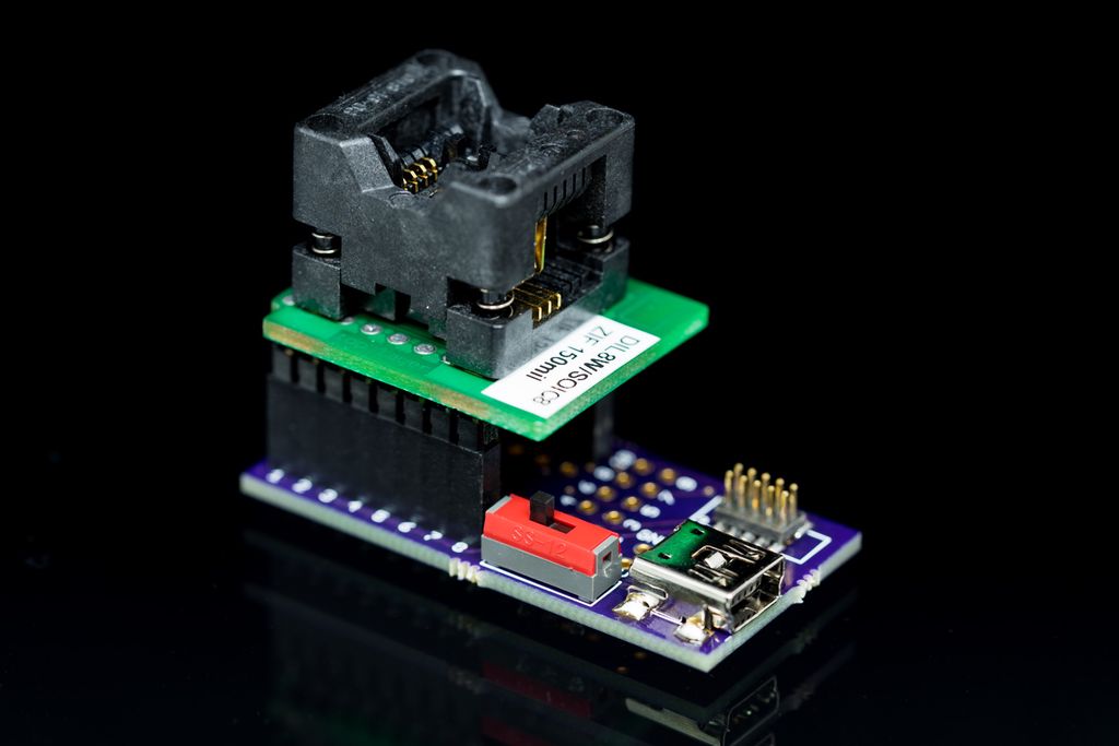
I built a compact ATtiny programming adapter to pre-program ATtiny13A chips before soldering, with a 50mil JTAG header, USB power, LED, and jumper options for other packages. I share EAGLE files, PCB ordering info and usage notes — read the post for photos, GitHub links and details.
Posted on 2019-07-13— C++, Improve your Code, Learn
I explain why I prefer #pragma once over macro header guards and how it prevents subtle build errors and wasted debugging time. I’ll show examples, common pitfalls, and practical steps to replace guards in existing projects — read on if you want a simple, low-risk improvement.
I walk you through assembling the gearbox for my 3D-printed cat feeder, step by step. I cover inserting insets, bearings, grub screws, and fitting the NEMA17 motor so the turntable runs smoothly. If you printed the parts from Part 1, follow along — read the full post for photos and testing tips.
I experimented with embedding whole PCBs, batteries and coils inside 3D prints to seal electronics invisibly in PETG parts. I explain pausing prints to insert components, then resuming, and share pros, cons and practical tips. Read the full post if you'd like step-by-step ideas and precautions.
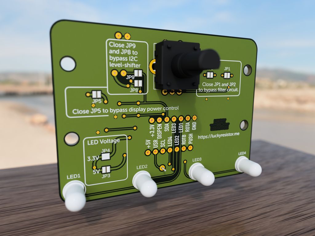
In Part 6 I walk you through the input panel for my 3D-printed pet feeder: the rotary encoder, LEDs, knob and the example PCB with wiring, filters and level shifting. I include printable files, Gerbers and ordering tips — read the full post for downloads, schematics and testing notes.