published: August 24, 2017 —
last modified: October 23, 2025
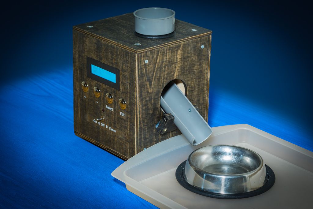
I finished a very simple and quick project recently. It is a programmable cat feeder device. The device is just made for one single portion, but it uses this slide which produces the distinctive sound if the pellets hit the bowl. It is no replacement for the usual feeding of the cat, but some flexible addition to give food out of the regular times.
The whole build was done in roughly four days, using a very quick prototyping and build method.
Design and Build Process
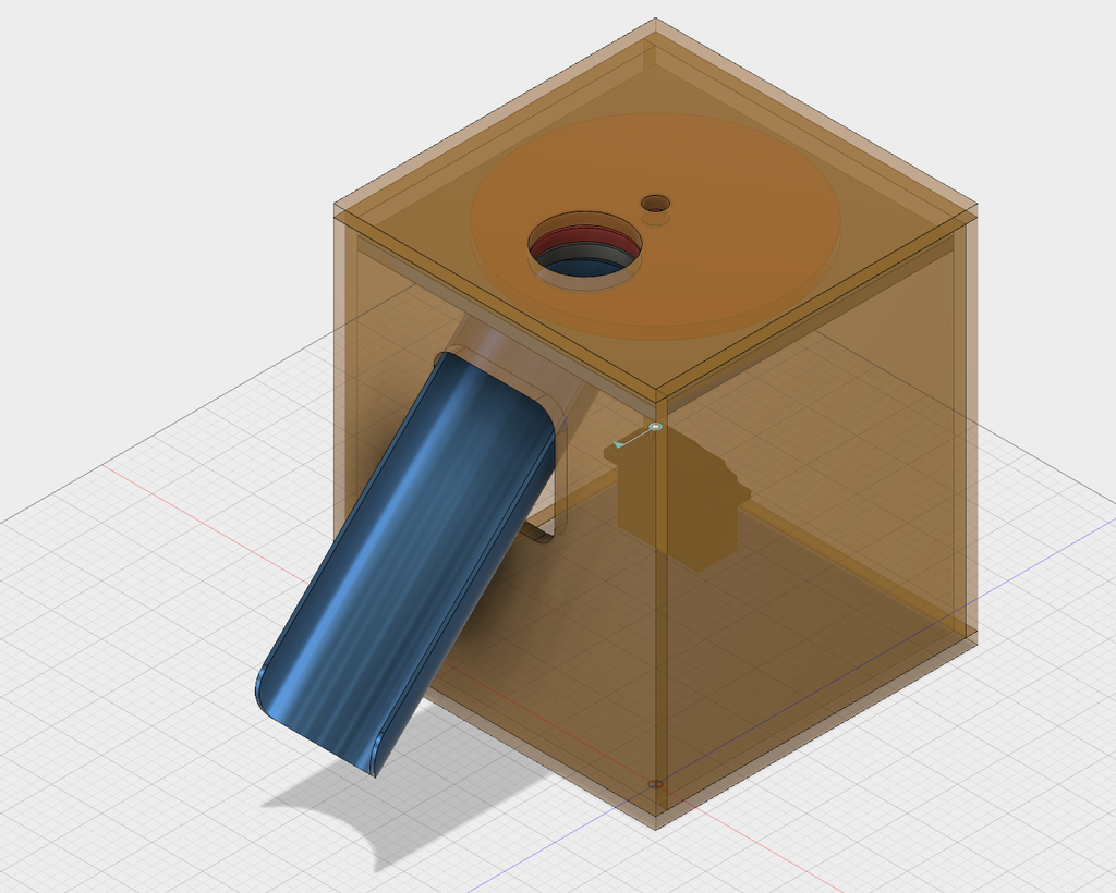
First I had to make a decision about the final size of the device. I used Autodesk Fusion360 to create a model of the device and try to fit all required parts into the device.
This is one of the last designs I made until I had the right size. I used a different mechanism as shown here, the important part was to get the right size.
Next I bought plywood in the right sizes for the outer shell of the case. I also got some additional panels fitting inside of the shell for the internal structure.
I created the shell with four sides, left the top and front side open. To work quickly I fastened the panels with hot glue in place. This has the benefit that you can remove panels using a hot air gun in the prototyping stage.
With the shell ready, I drilled all required holes into the panels of the shell and build the feeding mechanism with the servo into the shell.
Now it was time to build the front panel. Here I fastened the LCD display and buttons into this panel and fastened a platform to this panel where I was able to build the electronics on top.
After some tests if everything will fit into place, I added the final structures to the shell. I used wood cubes in all corners of the shell and used screws to fasten the panels. For the removable panels I drilled special screws into this cubes which contain a M4 thread. So I can fasten the removable lids using removable M4 screws.
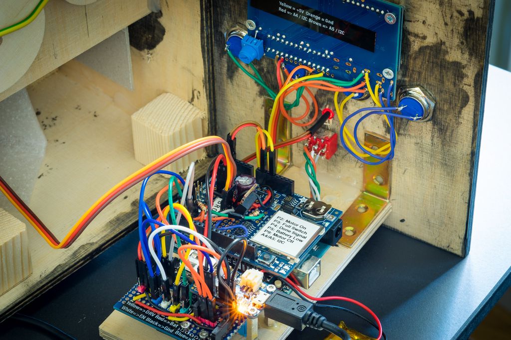
Now it was time to build the rest of the electronic components into place. I used M2.4 spacer which I glued with a two component glue into holes in the platform I build. This epoxy based glue is rock solid and is a very fast and solid way to fasten the break out boards on the platform.
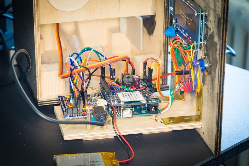
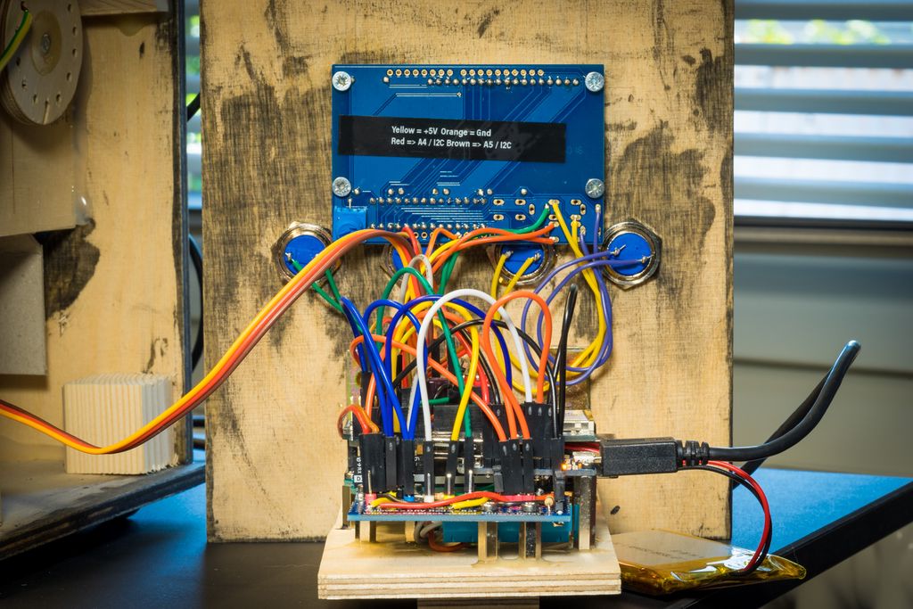
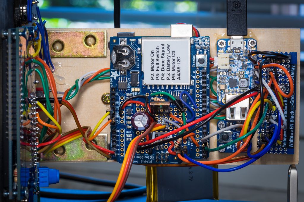
To build the electronic circuit I used a fast prototyping method. For this method I used an Arduino Uno with the Adafruit Data Logging shield with regular stacking headers. On all other break out boards I added pin headers. Everything is connected with jumper wires.
This method allows very drastic changes of the design without soldering. It is a very simple and efficient approach for a prototype. You can see in the previous image on the right side a special board with additional components. This board also contains pin headers for the connection to the other boards.
While building the device I noticed some issues with the Adafruit boards:
The TPL5110 timer supports a great one-shot timing mode. On this board, the required pin is fixed to VCC. There is no way to activate this nice mode. For my project, this would be exactly the required mode.
The Power Boost 500 charger is a very nice breakout board. I found this issues:
Instead of the many GND connections I would like to have the battery charge/full signal on one pin to put a LED into the front panel. Actually charging is not visible from outside of the device which is sad.
The pull-up resistor for the EN signal is a problem. There should be a cuttable trace on the back to disable this resistor or even use it as pull-down. This is especially useful in combination with the TPL5110 timer board.
The trimmer on the TPL5110 seems very nice, but actually it is useless with the large timing range of the chip. One usually like to have a very certain timing which is only possible with a fixed resistor. Maybe use the space to put two pads on the side where a resistor can be soldered direct on the board.
I really love the data logging shield with the prototyping area, it also contains a very nice RTC chip and also has a pad with the interrupt of this chip exposed! This interrupt is used to power my feeder device in case of an alarm. The only thing I would add here is a pad for the backup power of the RTC. In a device which is powered from a LiPo battery, one would like to power the RTC directly from the LiPo battery instead of a coin cell.
If you ever wrote firmware for a project with a LCD based menu system, you have be interested in the used firmware design. Also the source code contains an advanced driver for the PCF8523 chip, where you can access the full set of features of this chip.
If you have questions, miss some information or just have any feedback, feel free to add a comment below.
I created a readable, fully inline AES‑256/CBC implementation you can drop into C++ projects — handy for embedded systems. It avoids static S‑Boxes, needs only stdint/cstddef, and is MIT‑licensed on GitHub. If this sounds useful, read the full post for requirements, example code, and usage notes.
I swapped my LM386 for an NXP TDA7052 to reduce distortion and gain more volume. The TDA7052 needs only power, an input and connects to an 8Ω speaker; I added a volume trimmer (I used 47k, 10k also works). Read the full post for the schematic and wiring details.
I uncovered an ancient stone with a mysterious multiplexed display — five inputs and six outputs. In this puzzle I explore what the display likely represents and invite you to find the longest continuous sequence of numbers it can show. Try the interactive panel and read the full post to solve it.
Posted on 2019-07-08— C++, Improve your Code, Learn
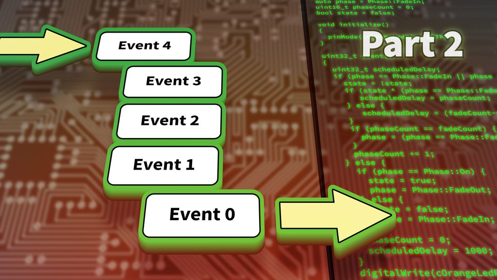
I guide you through evolving a simple Arduino blink example into a reusable event system. In Part 2 I cover function-pointer events, an EventLoop module, and practical multi-event examples. If you want cleaner, non-blocking firmware structure, read the full post for code and explanations.
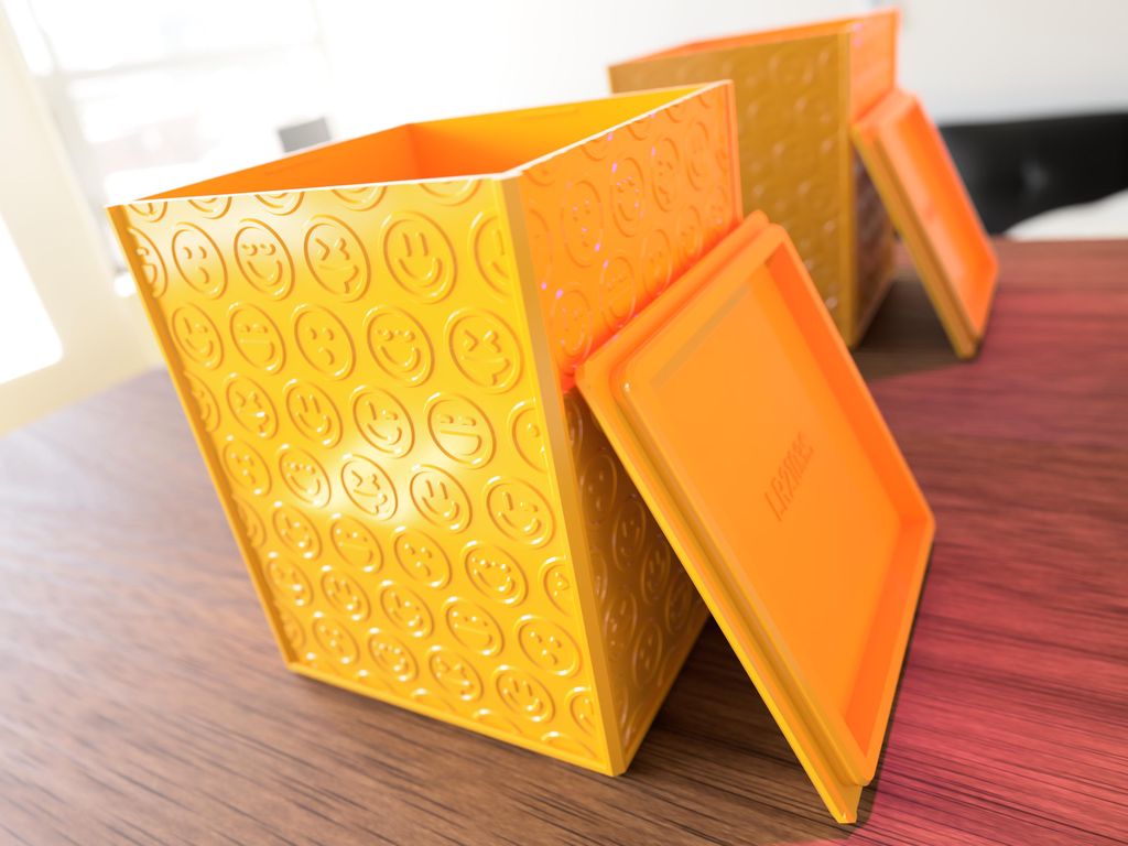
I've released a set of 500 3D-printable boxes decorated with smileys, each with two lid options and clear part-numbering to pick inner dimensions. I share printing tips, material recommendations, and a GitHub link for STL downloads—please read the full post for files and printing guidance.
I updated my pet-feeder's drive with a TMC2209 SilentStepStick and a 17HS19 stepper to get near‑silent operation and run from 5V. I built a simple Pico-based controller, adjusted gearing for speed, and tested sensors. Read the full update for photos, choices and test notes.