published: March 26, 2017 —
last modified: October 23, 2025
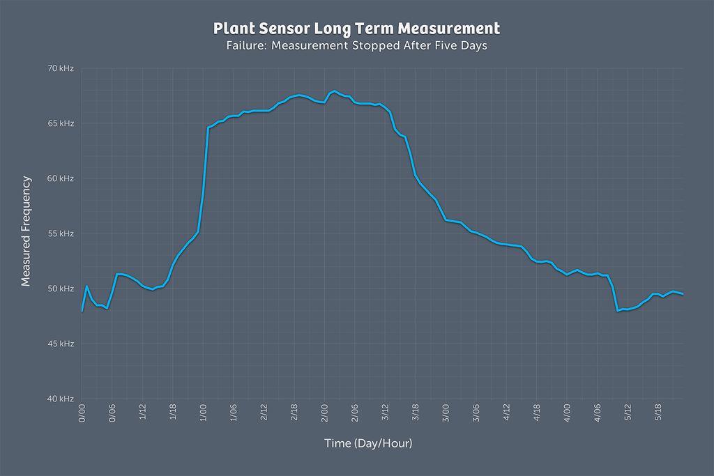
The first long term measurement I made, to test the behaviour of the sensor over a longer time range was a failure. After the five days with the device introduced in this post, the readings made absolute no sense.
The sensor was not moved in the flower pot and the plant was once watered at the begin of the measurement. While it looked promising at the begin, the frequency suddenly went down again, which was very irritating. I am still investigating how this could happen.
To get closer to the real measurement of the final plant watering sensor, I started a new approach.
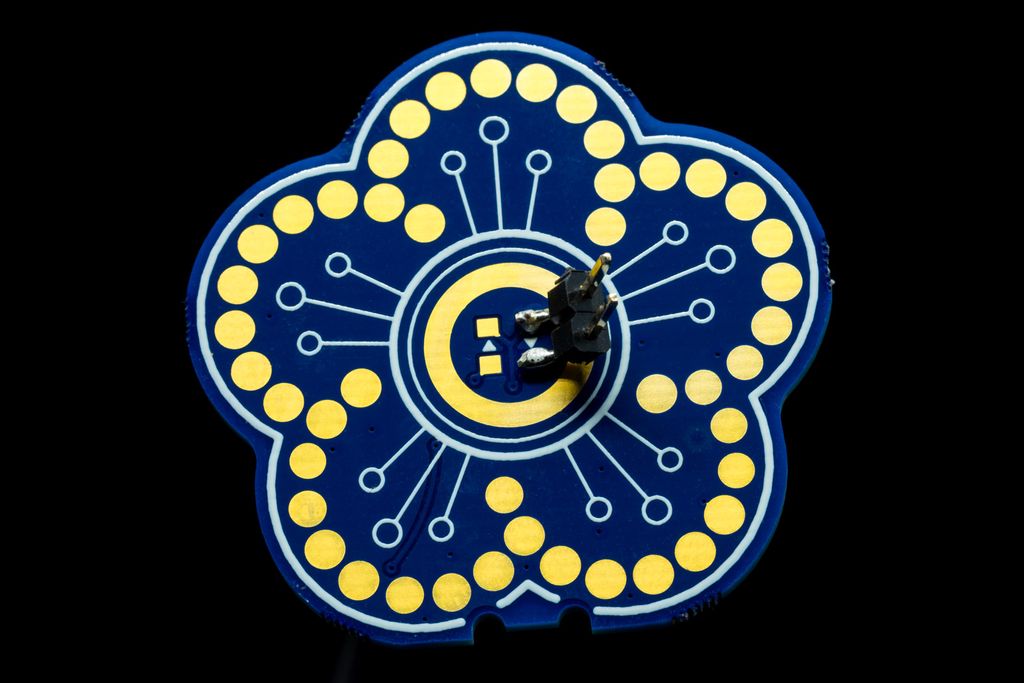
I soldered a header to one of the LED pads on a fully assembled plant sensor. Next I changed the device for the measurements.
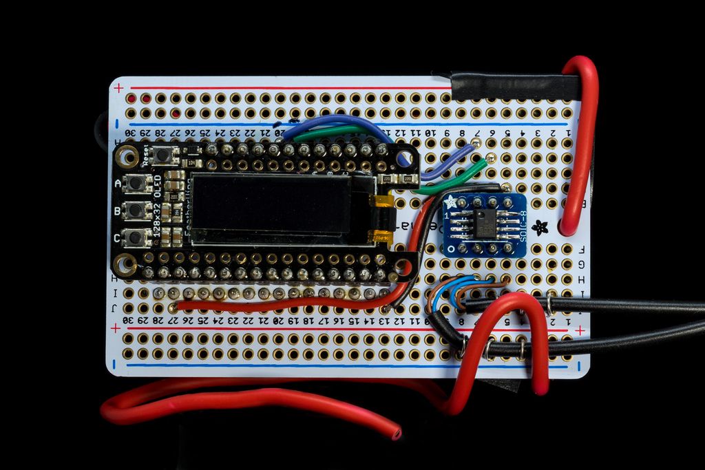
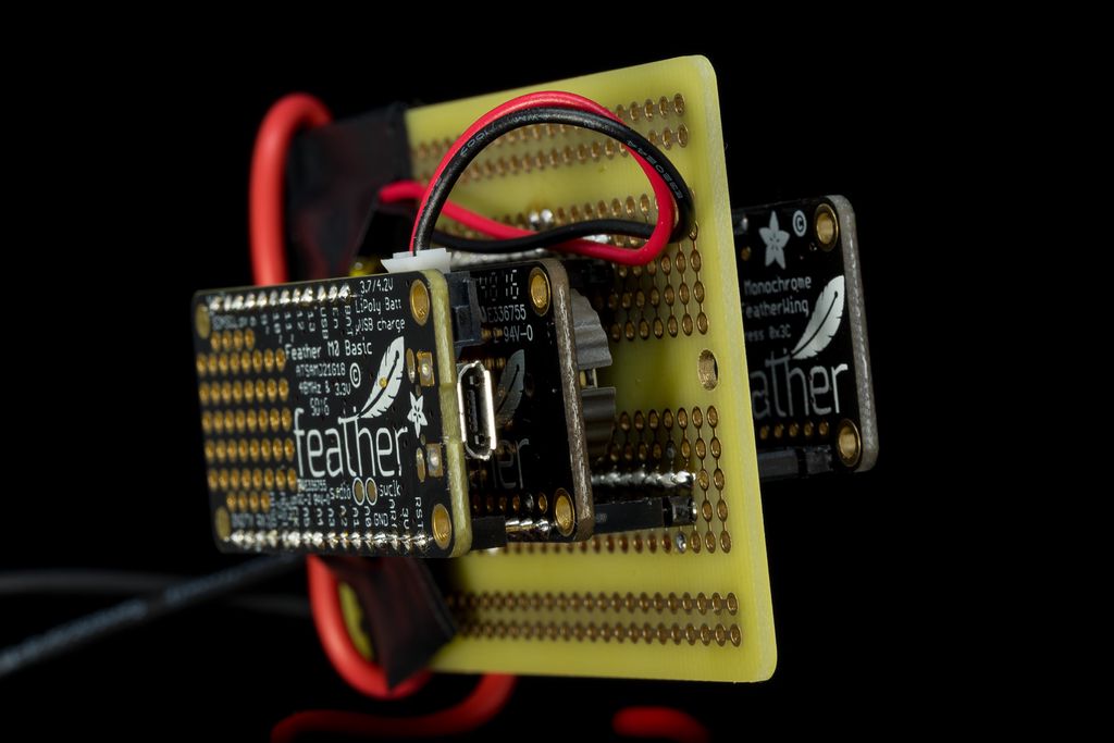
Next I added a small prototype board with matching headers for the Feather system and on top the OLED display.
I actually just added an optocoupler to receive signals from the plant watering sensor, but keep it completely insulated. To be able to compare two plant watering sensors, I prepared two inputs. For the first tests, I just like to repeat the long term measurements with one sensor.
A new firmware transfers the current values for the frequency measurement and the battery measurement using pulse length coding as used in the IrDA protocol. Here I use a very slow encoding, using a 1ms pulse for zeros and 2ms pulse for ones.
Code
The reason for this slow encoding is to use interrupts on the receiving side, without much impact to the rest of the code. There is plenty of time between the signal changes of this very slow encoding to process the bits and do all the other work. The plant sensor sends a signal every ~10s with 32bits, so there is no communication for a long time between this bursts.
Here the relevant code segments for the SAM D21 (Feather M0) to receive the bits from the plant sensor using an interrupt.
First I setup a timer to measure the time passed between the interrupts. The method setupCounter() initialises and starts the timer and the method readCounter() reads the current value of the timer.
The interrupt is setup using the attachInterupt() methods from the Arduino library. A method onInputChange() is called each time the state on one of the input pins changes. The logic in this method is very simple, it just checks how much time passed between a down/up signal change and shifts the bit into the variable gInputShiftValueA.
In the method readCurrentFrequency() I check if there are enough bits received, check the initial byte for the right value and convert the other bytes to the expected values.
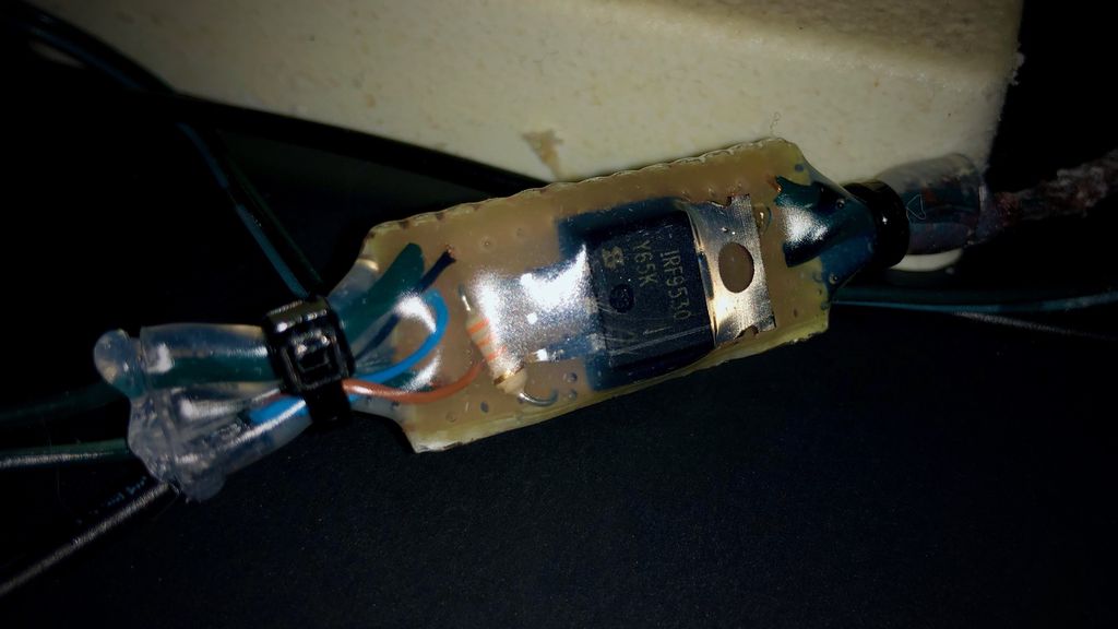
I wanted my winter decoration to switch on at dusk without constant adjustments, so I built a simple low-voltage controller using a P-channel MOSFET, a microcontroller and an ambient light sensor. I walk through my design choices, sealing for outdoor use and programming tips—read on if you'd like to build one too.
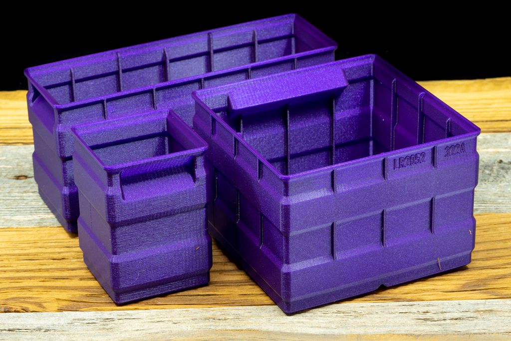
I've finished testing a new set of tall storage boxes designed for 3D printing. They're stackable with my flat and regular boxes, with reinforced walls and improved corners for cleaner prints. Download the free sample set or read the project page and catalog for full designs.
Posted on 2019-07-12— C++, Improve your Code, Learn
I walk through practical ways I use C++11's auto keyword to reduce repetitive declarations, simplify range-based for loops, lambdas and register access, and make Arduino and embedded code easier to refactor. Read the full post for examples and tips you can apply to your projects.
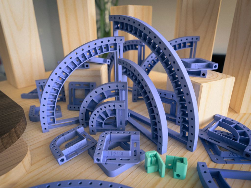
I designed a set of 3D-printable round corner templates specifically for woodworking and routing. They’re optimized for 0.4mm nozzles and 0.2mm layers, include snap-in guides, screw holes, and metric/imperial sizes. If you often rout rounded edges, read the full post for printing tips and mounting options.
I've released Lucky World, a compact jump'n'run for the MeggyJr RGB featuring an intro, 16+ levels, secrets and an end scene. I squeezed it into ATmega328P limits and shared the sources under GPLv2. If you're curious, please read on for downloads, requirements, and play instructions.
I show how a small C++ flags template makes embedded register bitmasks safer and much easier to read. I'll explain why macros and CMSIS-style definitions lead to errors, and walk through clear C++11 examples and a simple driver. Read on to see the implementation and usage.