published: September 21, 2016 —
last modified: October 23, 2025
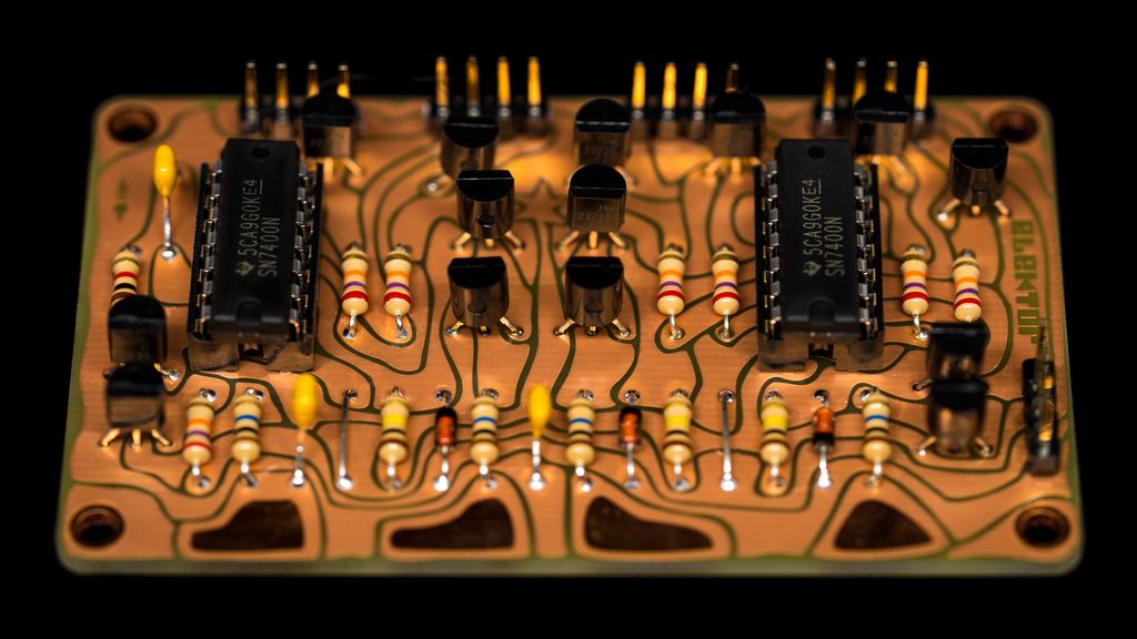
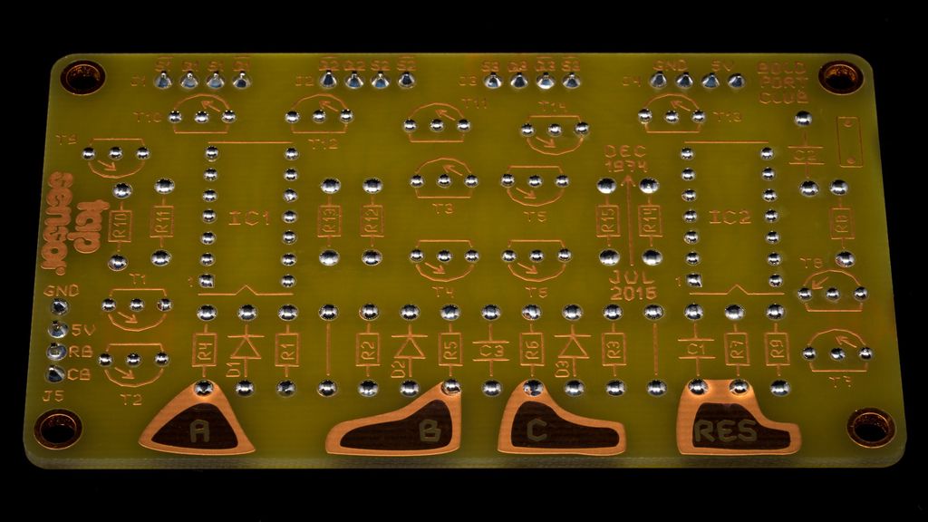
If you already saw the soldering video, here two photos of the result.
To get this result, I was inspired by the way Saar from Boldport was soldering his own projects, I adapted his technique.
After initial soldering, I flush cut carefully the wire as close as possible to the board. Cutting off any solder with the wire to make it flat.
Next I add more solder to the point until it forms a small round dome.
On the component side I add solder if necessary to fill the hole and make a smooth transition from the hole to the wire.
For this photos I use solder with lead – this is a huge exception. It is the only way to get this shiny domes. Normally I work with lead free components and solder according to ROHS.
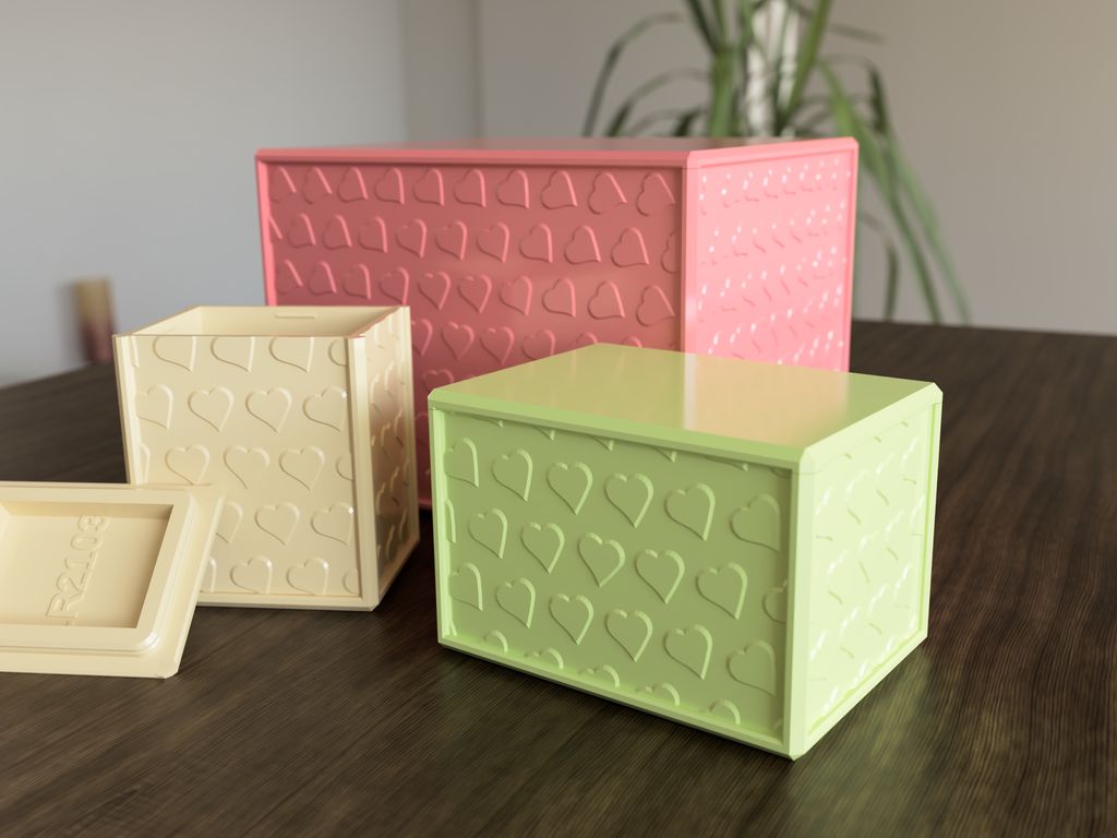
I tried parametric design and published a set of heart-decorated 3D-print boxes in 500 sizes (35–120 mm). I explain part numbering, two lid fits, and printing tips, and I've shared the STLs on GitHub. Read the full post to find the exact size and download files for your printer.
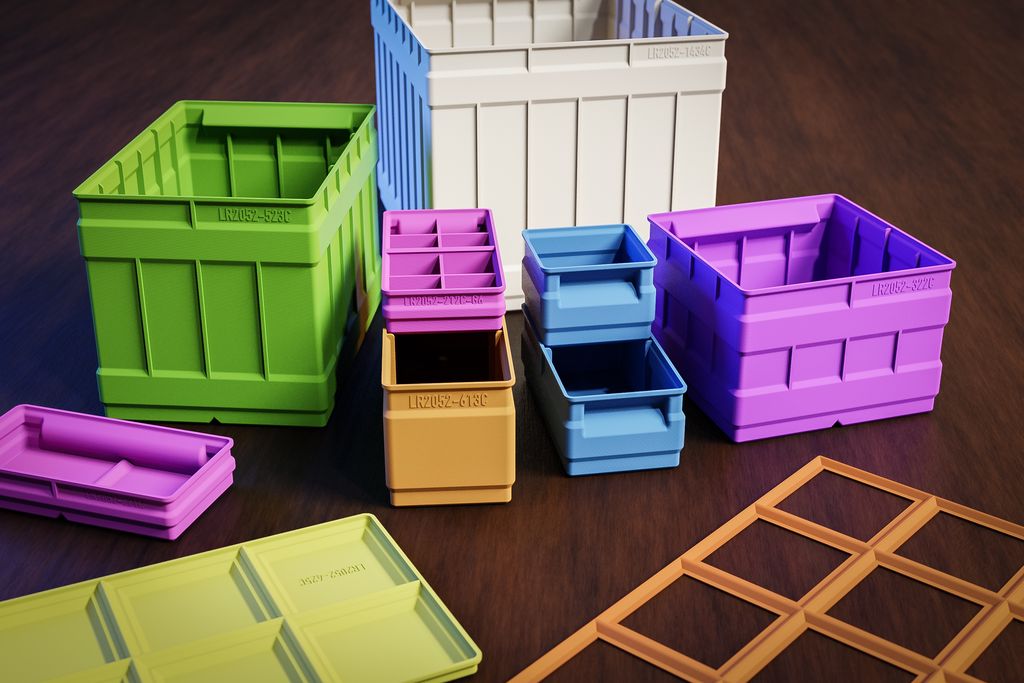
I’ve released a major update to my 3D-print storage box system: expanded sizes (up to 6x6 and 9x9 split), improved geometries, 3MF files, JPEG previews, and more dividers. If you use my boxes or print them yourself, read the full post for download links, compatibility notes, and printing tips.
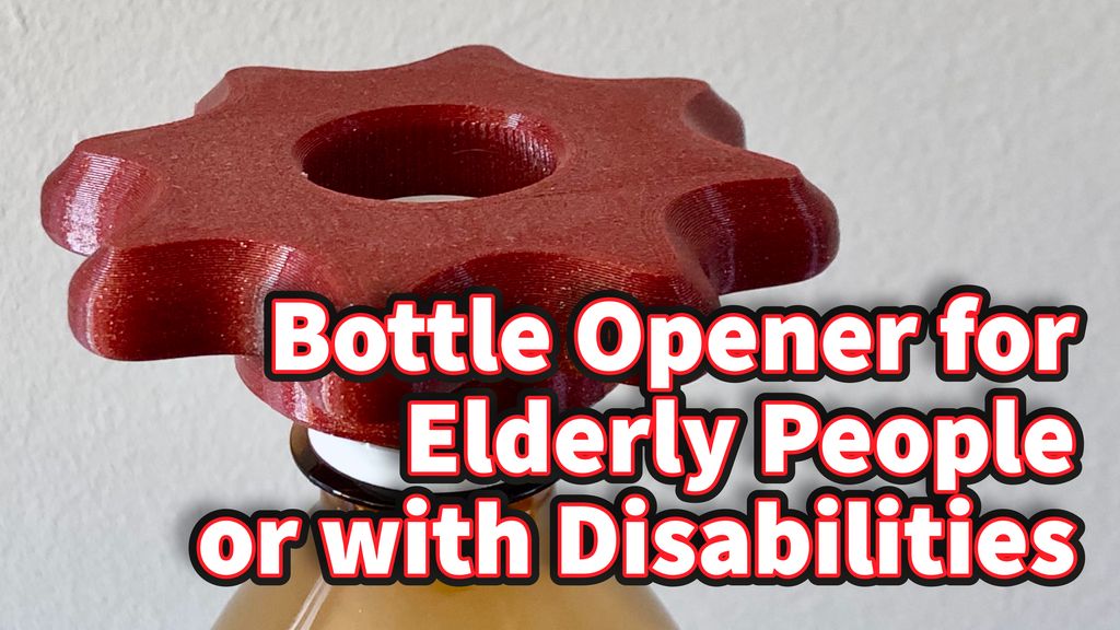
I designed a 3D-printable bottle opener to help seniors and people with limited grip turn 26–30mm plastic caps. The tapered 72-tooth socket adapts ±1mm and the handle has finger notches — print in PETG. Download the STL files and read the full post for print settings and tweaks.
I tested SeeedStudio's Fusion PCB service for a new prototype and ordered five blue, 2-layer FR‑4 boards with lead‑free HASL. Delivery took about 10 days and the boards showed good quality for the price. Read on for details about ordering, solder mask, and tolerances.
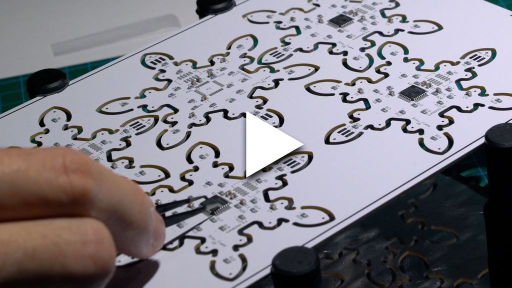
I walk through assembling the component side of my snowflake panel, showing stencil-applied solder paste, placement of 105 resistors, capacitors, headers and chips, and sped-up hot-air soldering. I test the LEDs at the end — please read/watch the full post if you'd like the complete build and tips.
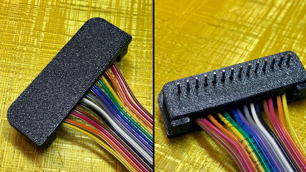
I needed a robust way to reuse a 14-pin header on different breadboards, so I designed a simple two-part 3D-printed enclosure, soldered a ribbon cable, and set the header in epoxy. Read on for my quick step-by-step guide and the downloadable design files if you'd like to try it.