published: September 8, 2016 —
last modified: October 23, 2025
I did many tests with the Outmoded Sequencer how to use steel balls as switches. While this is working very well from the electronic point of view, one problem was the steel balls tended to fall of the PCB easily and roll under furniture.
To hold the small steel balls into place I am building a matrix of 8×8 neodym magnets. This magnet matrix is later mounted below the PCB, so there will be one magnet for each pad on top.
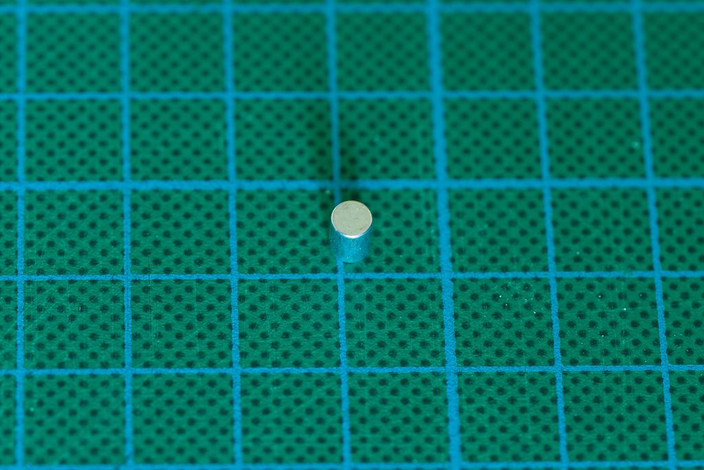
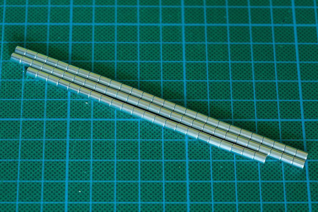
I am using these small, but very powerful neodym magnets. They have a diameter of 4 mm and a length of 5 mm. You can get this magnets, any many other shapes, from Supermagnete, they deliver the magnets to almost all European countries.
I started by using the holes in the PCB as a template to put marks onto a piece of plywood. Best is using a stitching awl, to create small holes. Next I drilled 64 holes with a diameter of 4 mm into the plywood.
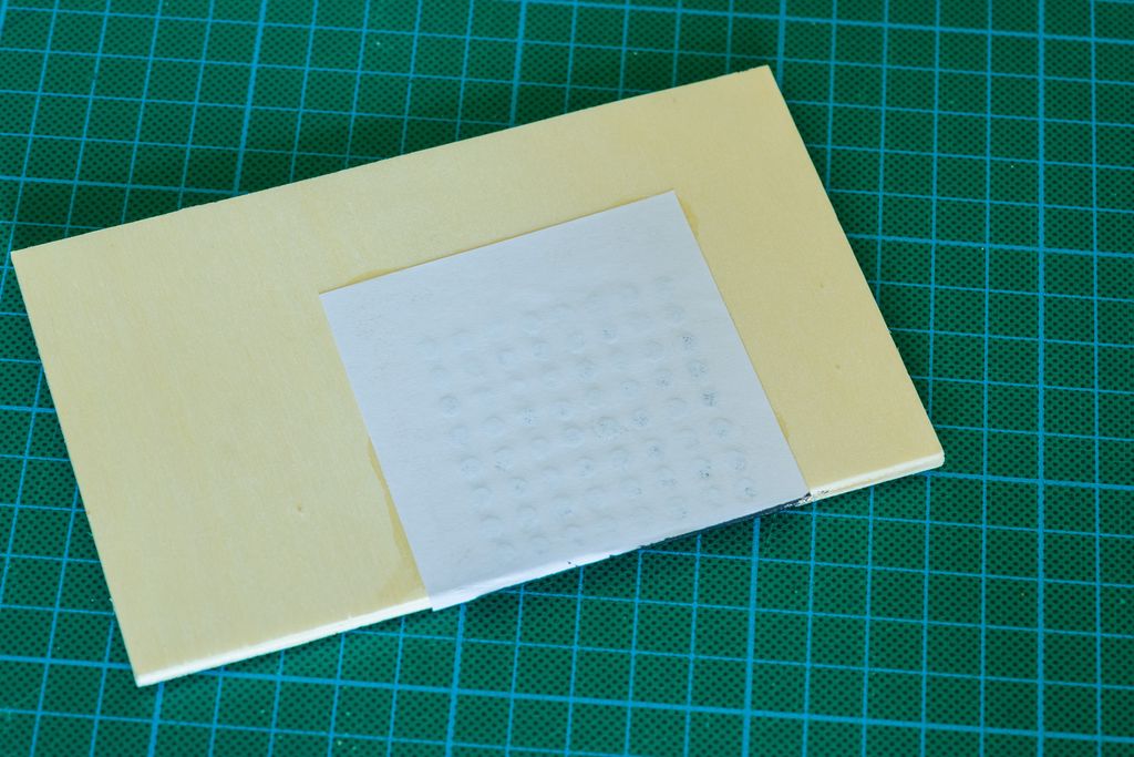
To fasten the magnets I glued a thin paper on one side of the plywood and put a small amount of glue into each hole from the other side. Then I placed one magnet in each hole.
This is very difficult, because this magnets are really strong and you have to keep them from leaving their holes and stick together. If the holes are precise made, the magnets can not move easily which prevents them from popping out of the holes.
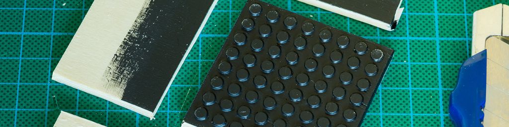
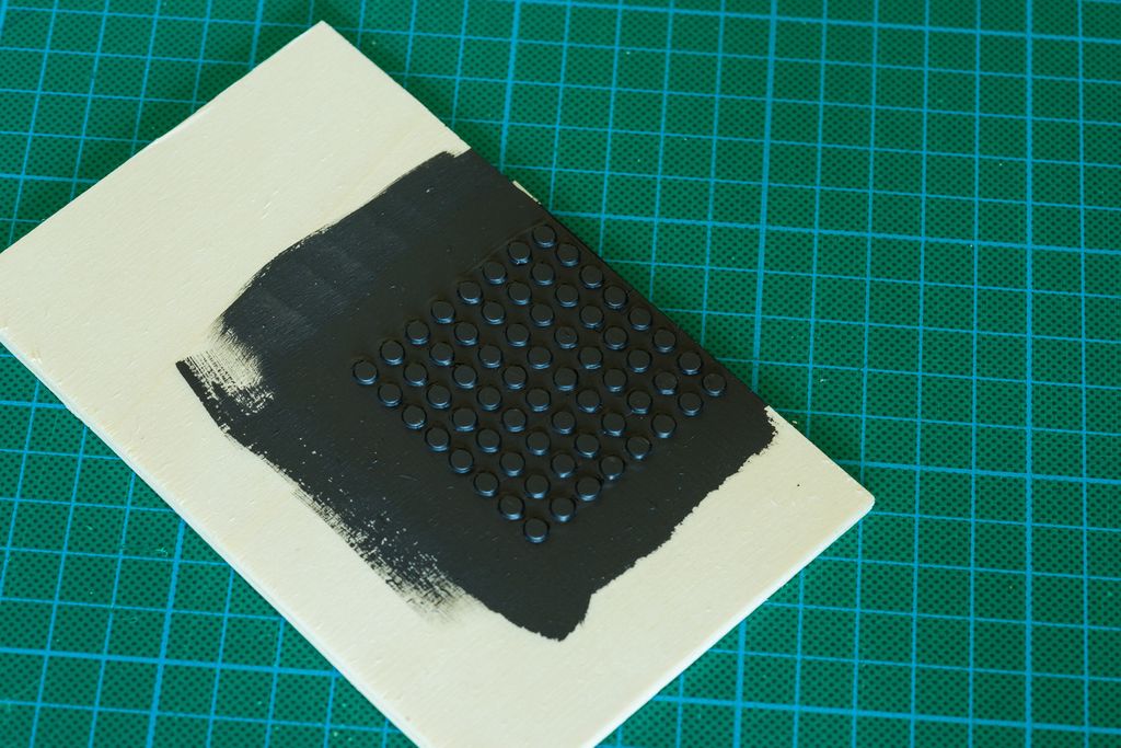
Next I added a thick layer of black acrylic paint on the wood and magnets from the other side. Dry acrylic paint gets very tough and will stop the magnets moving around.
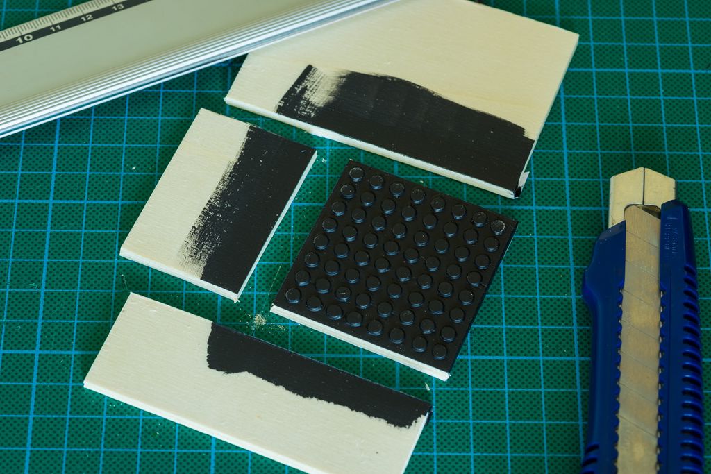
I let everything dry for 24 hours, then cut plywood to the final size. I used an utility knife to do this.
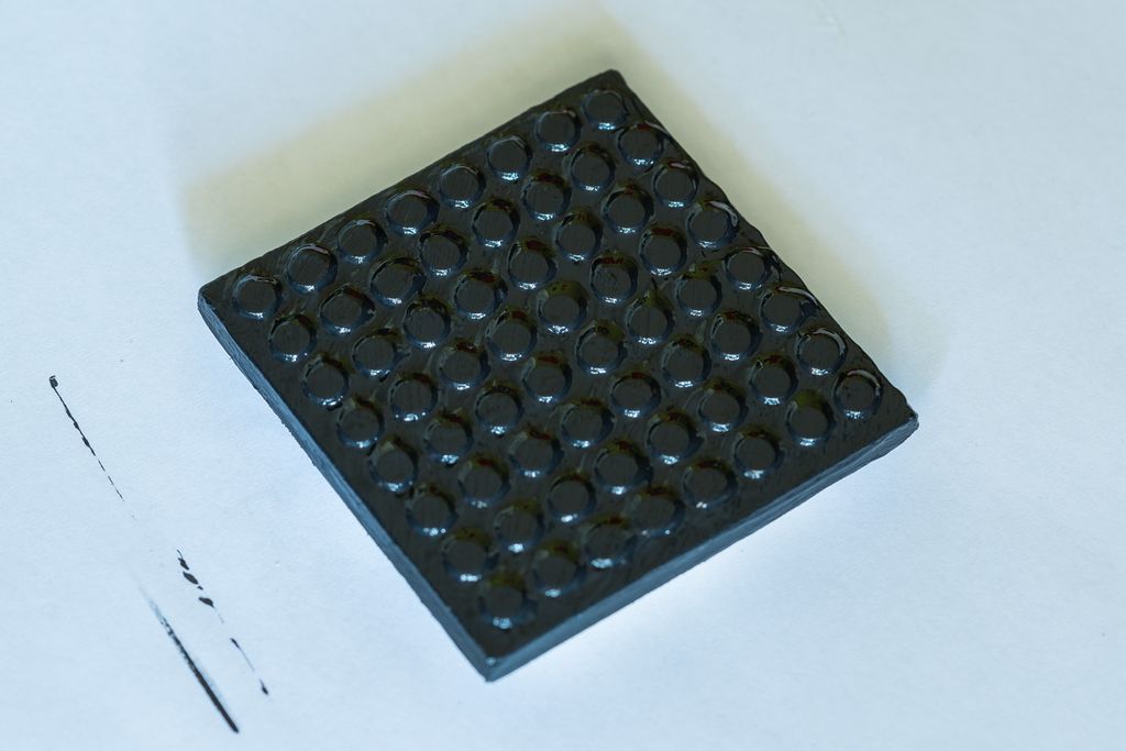
Now I added another layer of black acrylic paint. I also painted the other side of the magnet matrix which will be visible trough the holes of the PCB.
In the next step, I will bring the PCB of the outmoded sequencer into the right shape, by drilling the final holes into it. After this I just have to assemble and test everything.
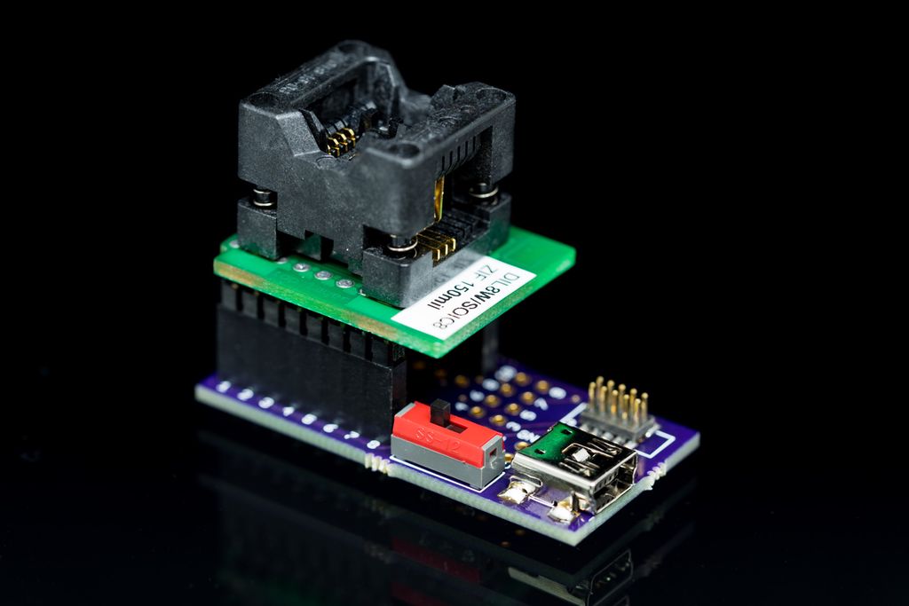
I built a compact ATtiny programming adapter to pre-program ATtiny13A chips before soldering, with a 50mil JTAG header, USB power, LED, and jumper options for other packages. I share EAGLE files, PCB ordering info and usage notes — read the post for photos, GitHub links and details.
Posted on 2019-07-13— C++, Improve your Code, Learn
I explain why I prefer #pragma once over macro header guards and how it prevents subtle build errors and wasted debugging time. I’ll show examples, common pitfalls, and practical steps to replace guards in existing projects — read on if you want a simple, low-risk improvement.
I’ll walk you through creating custom patterns for your snowflake decoration, covering double-buffering, frame-sync, non-linear PWM, fixed-point math and the scene interface in C++. If you can solder and use an SWD programmer, read on for practical examples and a ready-to-edit User scene template.
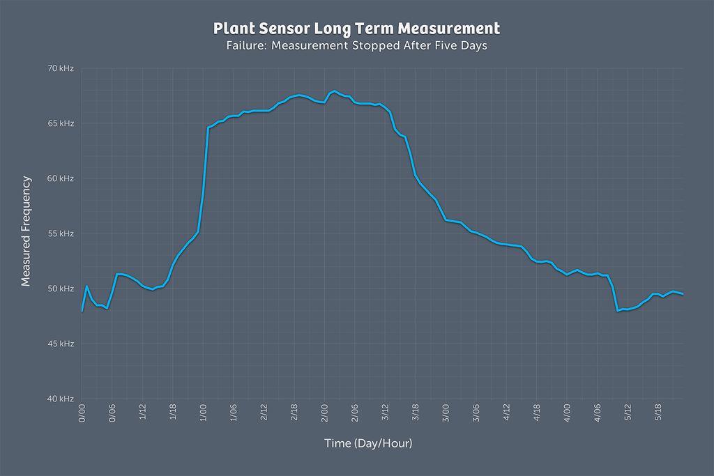
I ran a five-day long test of my plant watering sensor and the results were confusing, so I started a new, more insulated setup using an Adafruit Feather M0, an optocoupler, and pulse-length encoded signals with interrupts. If you’re interested in the hardware and code details, read the full write-up.
I developed a small application that generates randomized circle patterns inside a defined rectangle, letting you tweak width, height, precision, spacing and item counts. Results export to SVG and the latest version is available for download. Read the full post for interface details and usage tips.
I’ve published a simple firmware example for the Always-On project, built for PlatformIO and Visual Studio Code with my HAL adapted for Adafruit Feather M0. It explains the hardware mapping, motion-triggered lighting behavior, and timing options. Please read the full post for setup instructions and the GitHub link.