published: September 5, 2016 —
last modified: October 23, 2025
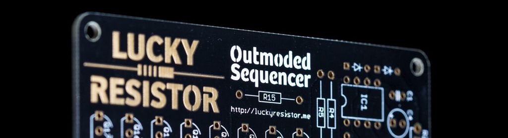
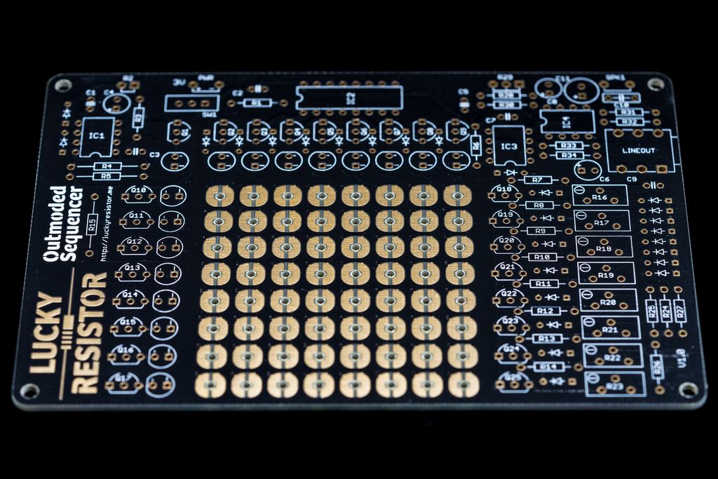
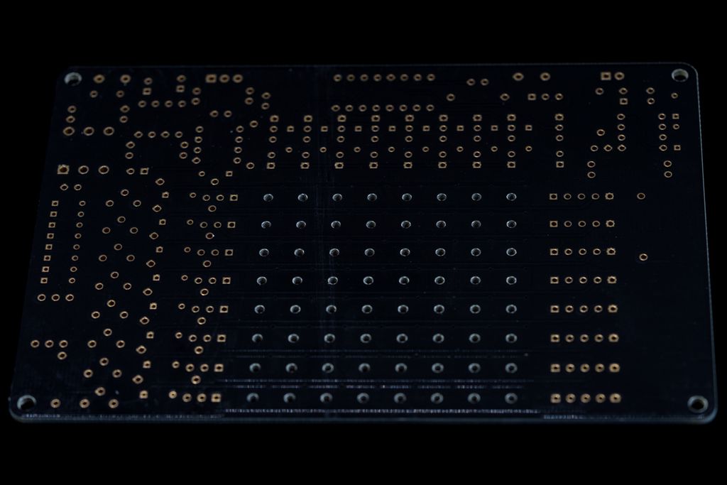
The final black and gold PCBs for the Outmoded Sequencer arrived. They really look great with a nice contrast between the solder mask and the silk. The surface is somehow glossy and the routes are barely visible under the black solder mask. Now I really hope I will not find any further problems with this PCB.
This nice PCBs were produced by PCBWay. As you can see, the quality of the PCB is very good. They produced it in three working days and it was shipped in three days via DHL.
The final version is 8mm wider and 10mm higher than the prototype PCB. You can also see how I rearranged the components to move the matrix more to the center.
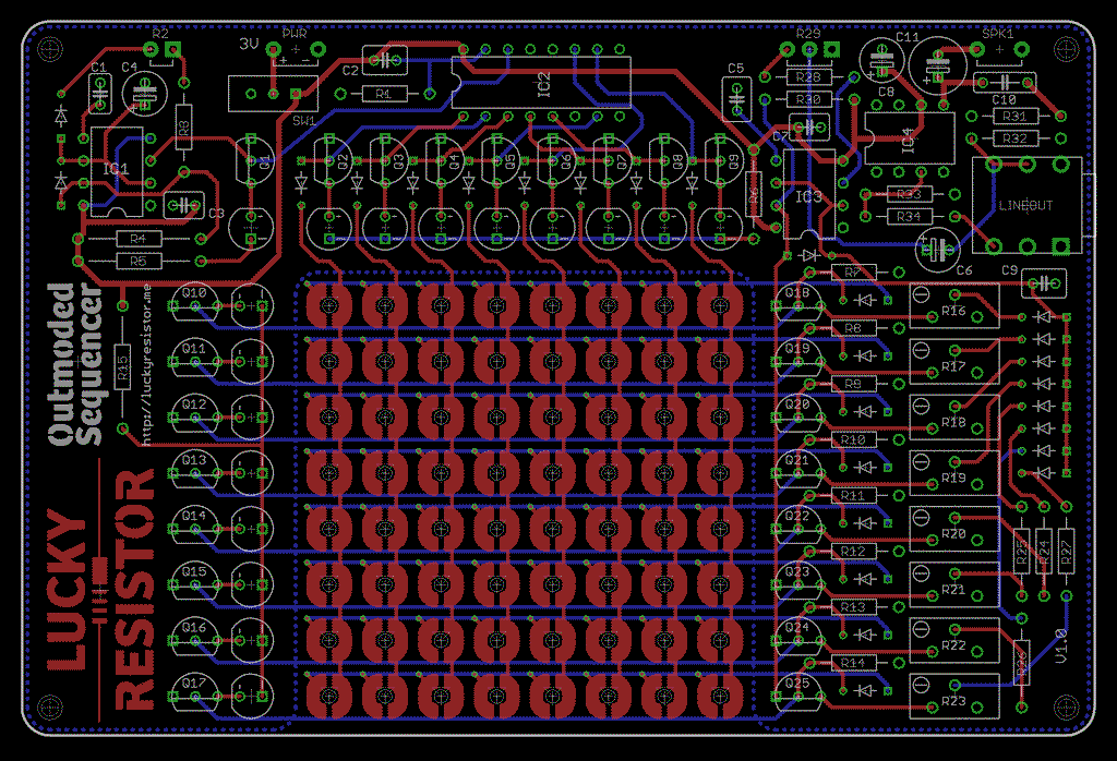
A very interesting fact is, that I could simplify the routing, because I mounted the resistors and diodes back in the normal horizontal way. This created space under the components which I could use for the routes. Here the routing of the final board:
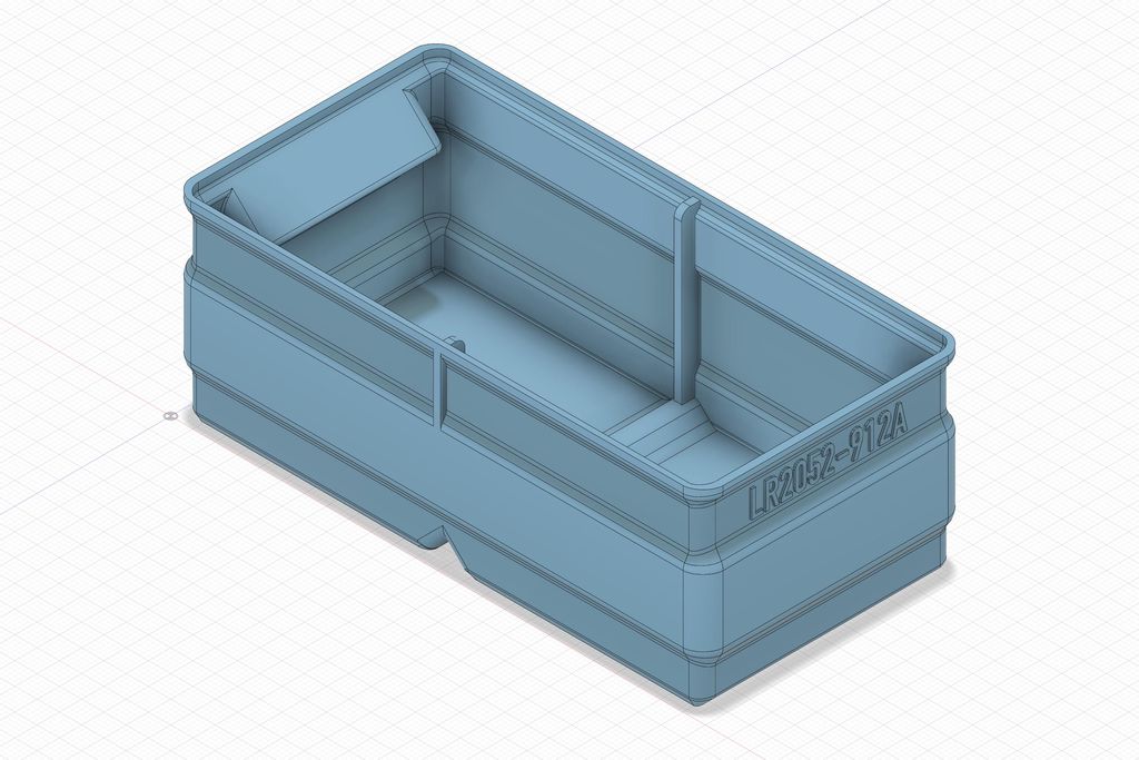
I designed an experimental storage box for 45° belt printing and shared the STL for others to try. I haven't printed it myself, so it's a best-guess layout optimized for 0.2mm layer height and common nozzles. If you have a belt printer, please test it and tell me how it performs, and read on for details.
Posted on 2019-08-05— C++, Improve your Code, Learn
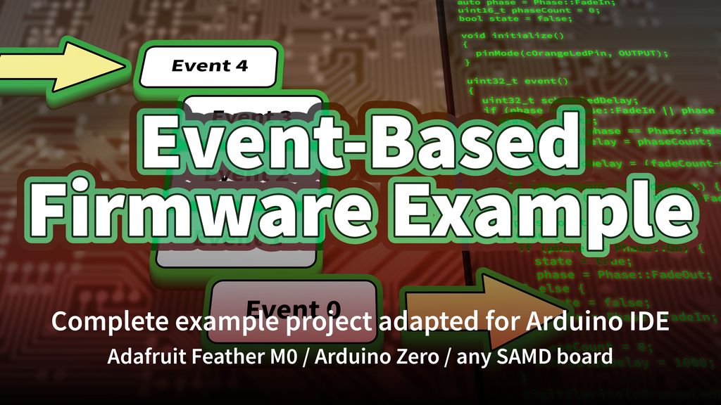
I provide a complete event-loop firmware example for SAM‑D boards (Arduino Zero, Feather M0). I explain module design—Buttons, Display, and a support library—initialisation and polling logic, and link the source and demo. If you're curious, read the full post for code and implementation notes.
I created a logic-gate puzzle featuring a gated D latch: more artwork than optimized circuitry. I invite you to try decoding the hidden message—there are hints and links to gate and flip-flop basics in the post. I hope you enjoy the challenge; read the full article if you'd like to solve it.
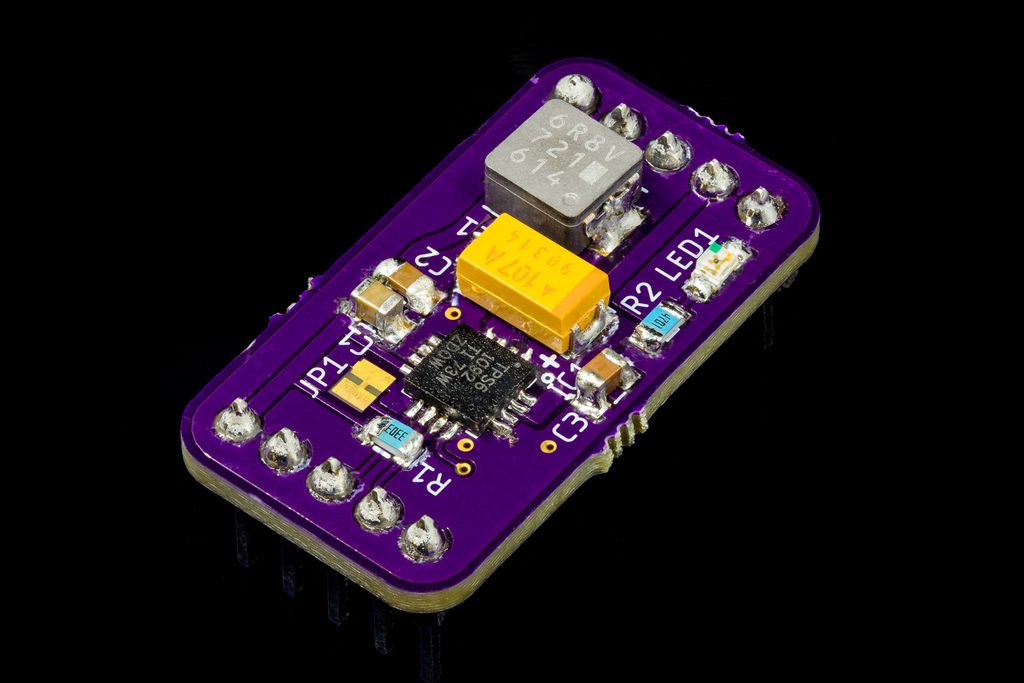
I built a small test board for the TPS61092 to evaluate thermal performance, hand‑solderability, and layout before using it in my project. The chip stayed cool under 0.5A and the OSH Park PCB looked great. Read on for measurements, the BOM, and practical soldering tips if you want to try it.
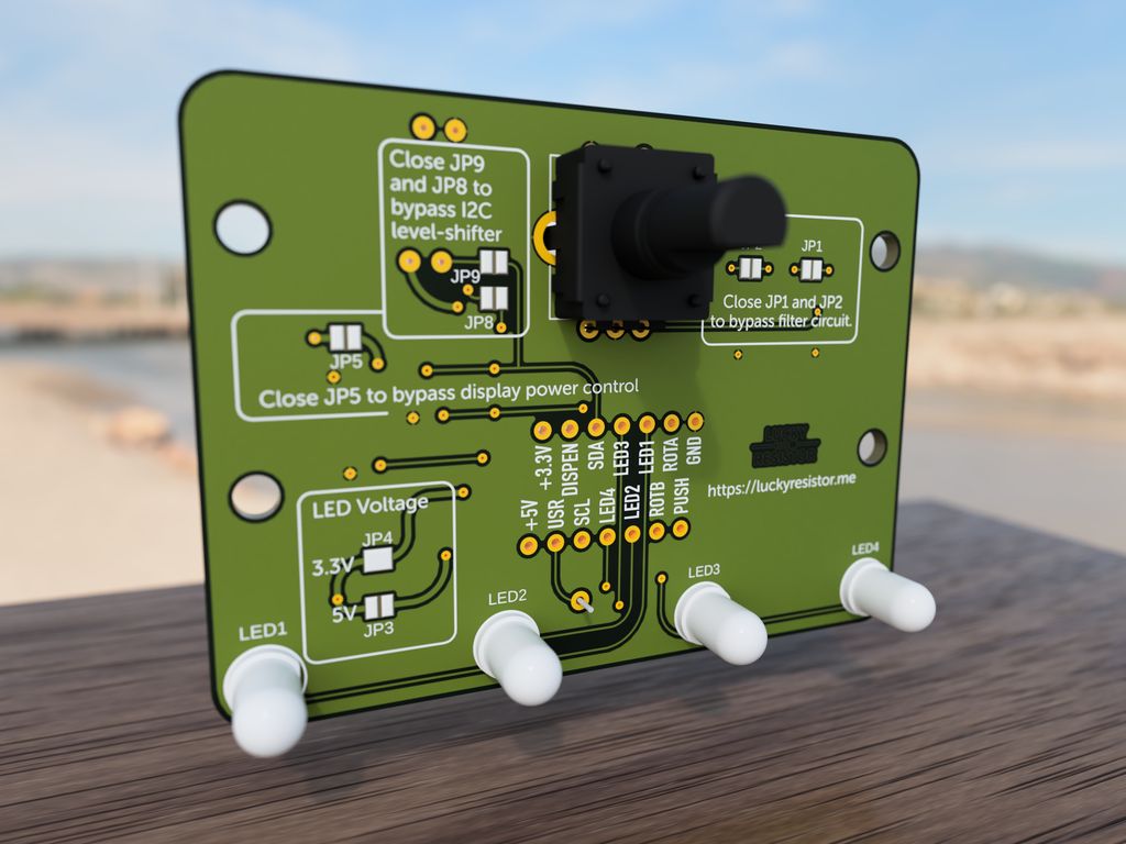
In Part 6 I walk you through the input panel for my 3D-printed pet feeder: the rotary encoder, LEDs, knob and the example PCB with wiring, filters and level shifting. I include printable files, Gerbers and ordering tips — read the full post for downloads, schematics and testing notes.
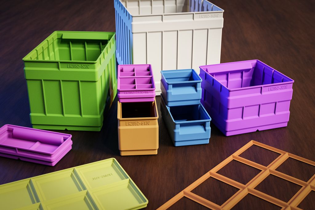
I’ve released a major update to my 3D-print storage box system: expanded sizes (up to 6x6 and 9x9 split), improved geometries, 3MF files, JPEG previews, and more dividers. If you use my boxes or print them yourself, read the full post for download links, compatibility notes, and printing tips.