Are My Documents Safe in the Root Cellar at ~80% Humidity?
published: August 20, 2015 —
last modified: October 23, 2025
Update 2015-08-21: Added the wiring diagram.
Update 2015-08-24: The documentation for the minimal version is online here.
There is a large cellar where I could store unused items and documents, but the catch is the humidity there. It is a root cellar near a small brook and the humidity varies between 75% up to 90%.
Archived material should never be exposed to humidity greater than 65%, therefore I have to isolate all documents in boxes from the air of the cellar. But are this boxes safe? Do they keep the humidity away from the documents – even for years?
To have a look into the box environment, I need a data logger. It would be simple to buy one, but much more fun to build one. So a new project is born: I call it the “Data Logger” project.
There are a few phases to realise this project:
Prototype (done)
Simple Version (in work)
Deluxe Version with Display and Case
The Prototype
For the prototype I used a large solderless breadboard from 3M. There I actually just tested the components for the simple version, especially if the protocols are working and if I can use them in the way intended. I will keep this section short and explain everything in detail in the next section. Just to remind you, I tested everything on a breadboard before I soldered the components to a stripboard.
Parts of The Simple Version
The simple version should be a data logger which automatically starts logging temperature and humidity values it it is powered on. Using a small switch, I can select between logging, reading and erase. In the reading mode, the logger will send all logged values to the serial interface.
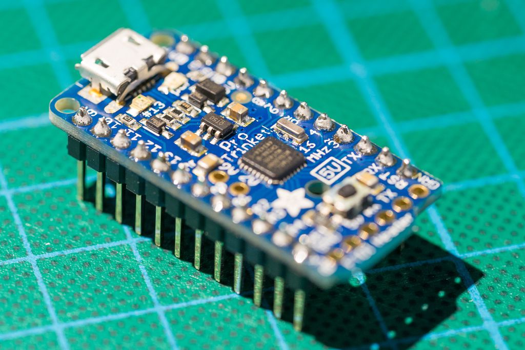
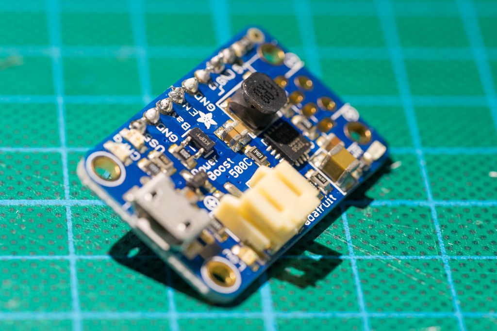
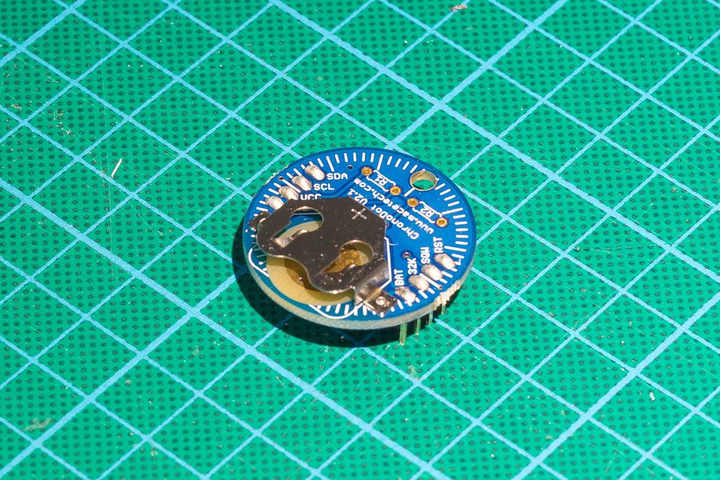
Because I need quick results, I will build the whole device using components from Adafruit. Here a list of components I will use for the simple version of the data logger:
These components have an excellent quality. The price today for all the components above is $97. You can buy a similar data logger for approximate $80, e.g. the RHT10 from Extech. Just to make clear this project is more for fun. If you need a cheap solution, better buy a cheap one from Amazon.
There are other components I use which should be available in every electronic lab:
Stripboard
Wires
Pin Headers
Crimps and Crimp Sockets
Switches, DIP Switches, etc.
Building the Simple Version
I will publish a complete wiring diagram for the data logger later. The following guide is therefore just a demonstration how I build the device. I start with the critical components, then test everything before I add more components.
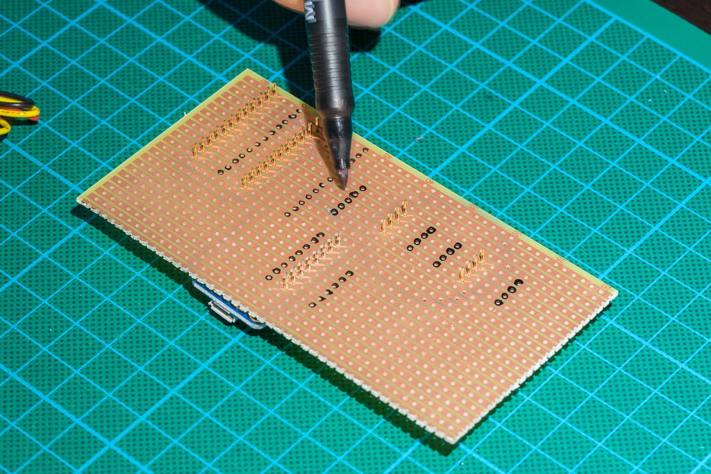
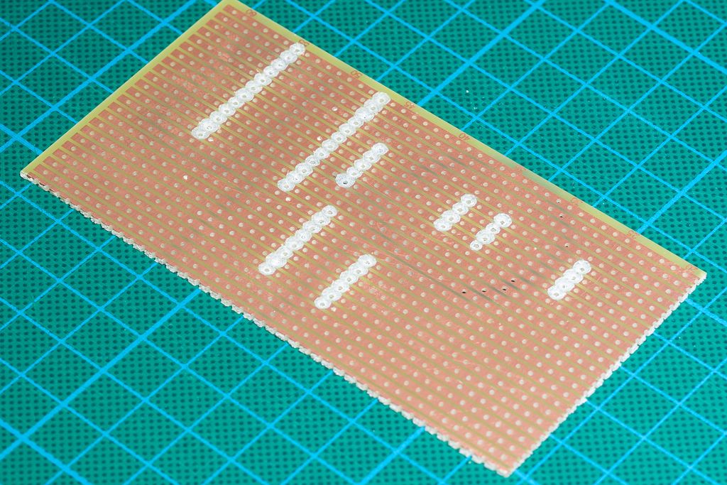
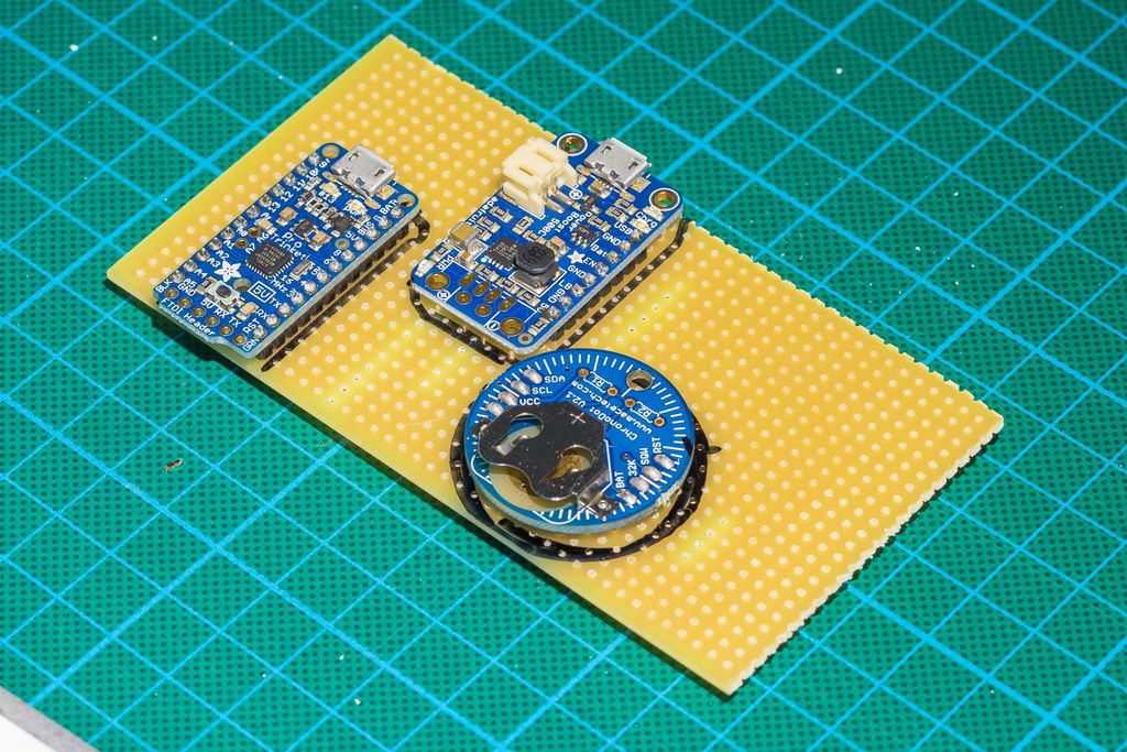
First I put all main components on the board in the best possible way, mark the outlines of the components, turn the board around and mark the points where I plan to cut the stripes.
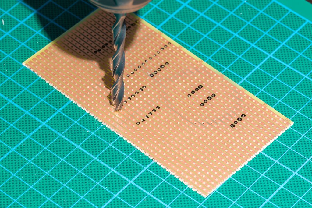
I am using a drill to cut the stripes. There has to be a better tool to just cut the stripes, but actually I never found a good one.
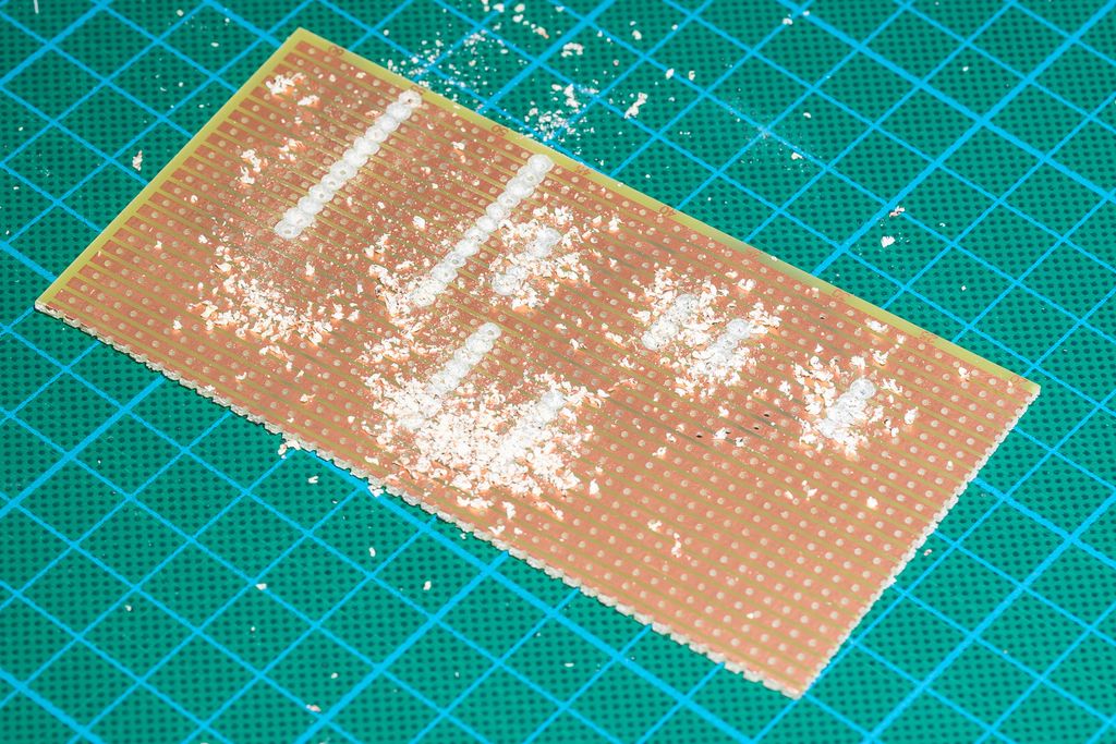
Some cleaning-up is required after this process.
The result. Now I verify if all marked stripes are completely cut and no copper is left on the board.
I put the components back at the marked locations. Make sure you not only mark the location, also the orientation, e.g. of the USB port.
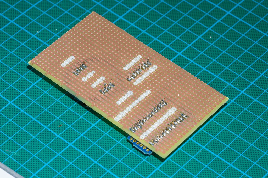
Now I solder the components into place and shorten the pins to a good length. If you plan to reuse these components, please use a female pin headers on the board. It is almost impossible to remove the components if they are soldered in this way to the board.
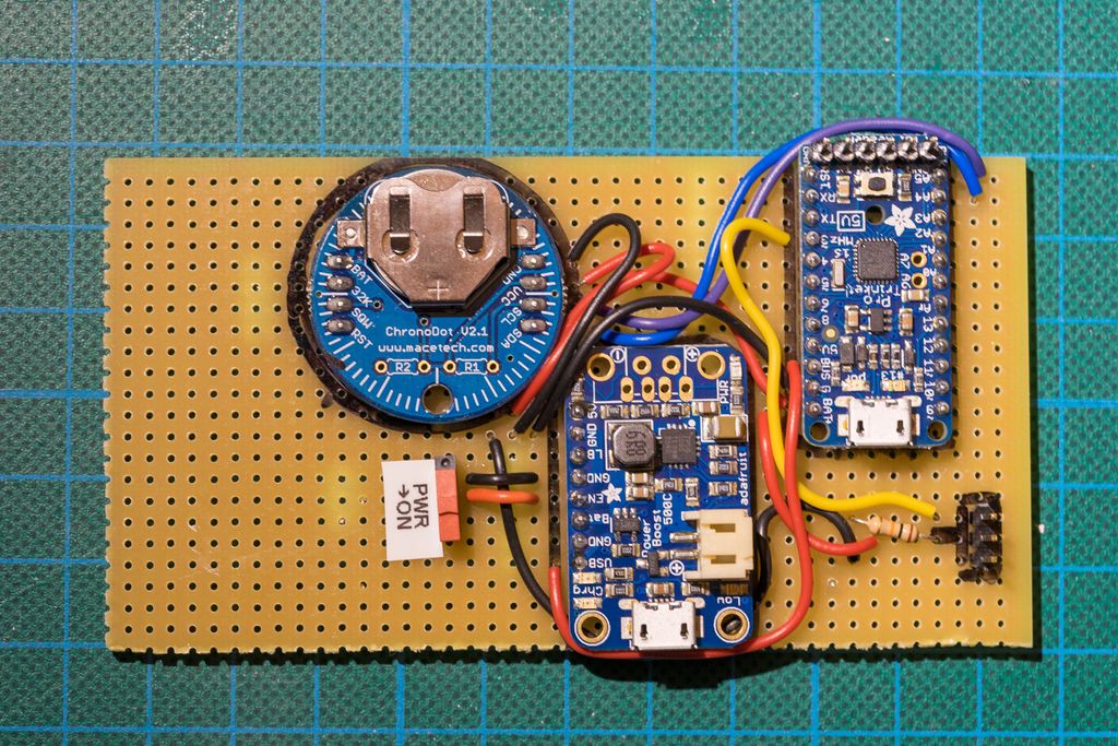
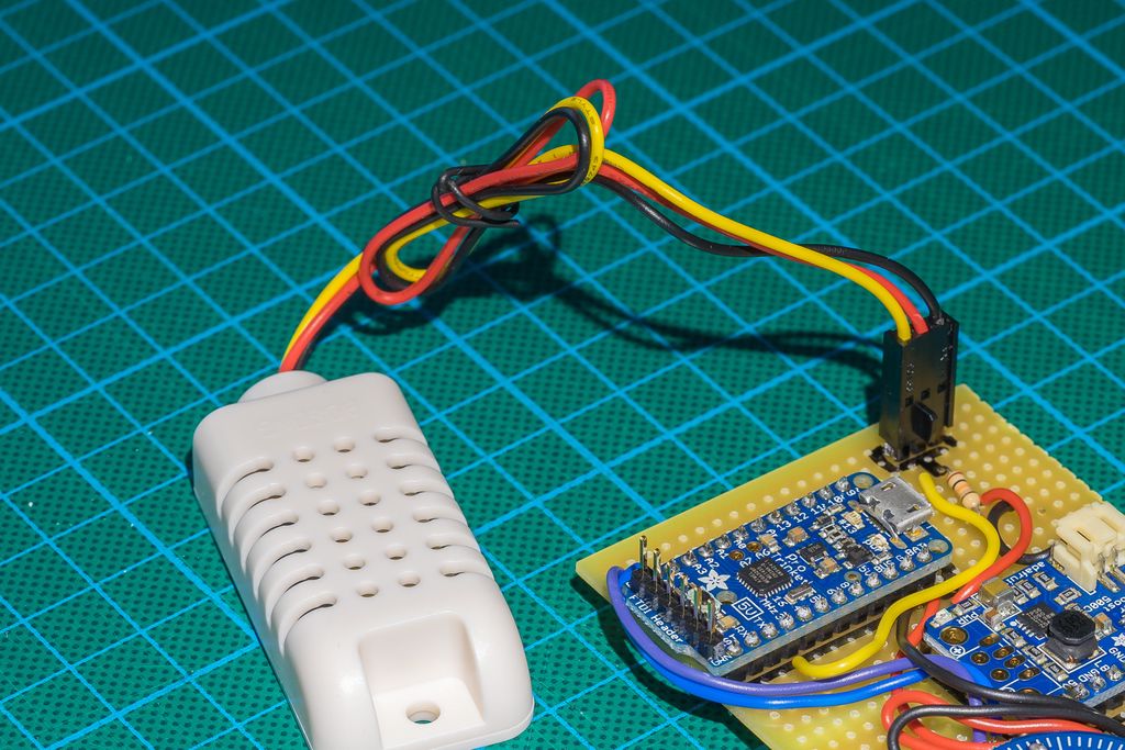
Now I add all wires. I use red for power 5V, black for GND, yellow, violett and blue for the sensor data wires, and orange for the power-off signal.
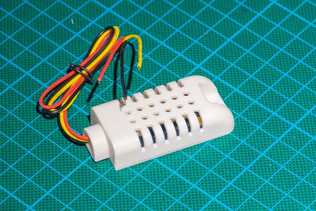
To connect the sensor itself, I use a pin header with three pins and use crimps and a crimp housing to attach a connector to the sensor. I should probably write an article about crimps, they are really useful.
Testing the Core Components
At this point I connect everything and use the Arduino IDE to write some simple programs to test the components. Everything is working fine and this is the current state of the project.
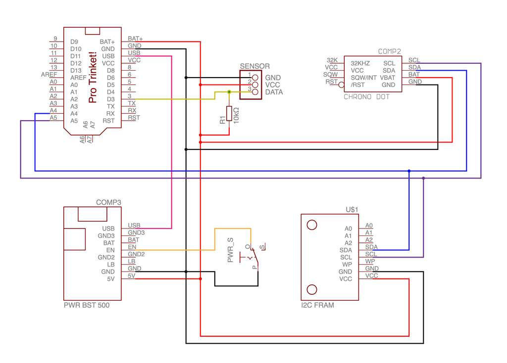
Wiring Diagram
Here the wiring diagram for the simple version of the data logger. I changed the colours of the wires according to the wire colours I used on the device board.
Whats Next?
The next steps will be:
Adding the FRAM to the board.
Writing the final software for the simple version.
Follow my blog to get a notification when I publish the next steps of the project.
I wanted to capture the tiny, spiky corona of light from a snowflake decoration on video and found it challenging. After experiments I developed a simple effect that better conveys the sparkling as seen by the eye. Read on to see my approach, results, and how you can try it yourself.
I've released Lucky World, a compact jump'n'run for the MeggyJr RGB featuring an intro, 16+ levels, secrets and an end scene. I squeezed it into ATmega328P limits and shared the sources under GPLv2. If you're curious, please read on for downloads, requirements, and play instructions.
I’ve published a simple firmware example for the Always-On project, built for PlatformIO and Visual Studio Code with my HAL adapted for Adafruit Feather M0. It explains the hardware mapping, motion-triggered lighting behavior, and timing options. Please read the full post for setup instructions and the GitHub link.
I describe making a small alpha batch of my low-cost plant-watering sensor: ordering parts, prepping and soldering wires, testing PCB assembly with stencils, and solving sealing with epoxy. If you’re interested in practical prototyping tips and lessons learned, please read the full post for photos and detailed steps.
Posted on 2019-08-01— C++, Improve your Code, Learn
I walk through practical techniques I use to make firmware error handling clearer and more consistent in modern C++. From enum classes and a shared SimpleStatus to StatusResult templates and helpers like isSuccessful, I present readable patterns and code examples you can adopt. Read the full post for details and examples.
I walk through assembling the component side of my snowflake panel, showing stencil-applied solder paste, placement of 105 resistors, capacitors, headers and chips, and sped-up hot-air soldering. I test the LEDs at the end — please read/watch the full post if you'd like the complete build and tips.