I got questions about a particular feature you find if some of my 3D models. In this short text, I will explain why I add it and why you should add features like this too.
How the Features Look Like
Please check out my latest modular lantern design if you want to see the technique in actual models. In part LR2268-22-B, you find it at the top of the groove for attachments:
In part LR2268-23-B, you can see it at the top of the space where the side panels lock into the lid.
The Problem with Bridging
Look at the following simple part you like to print with PETG:
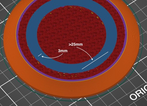
There is bridging involved, but with 3mm at the top of the groove, it should not pose a problem. Yet, if you look at the result the slicer generates, you notice the problem.
The slicer creates a bridging area over the gap at a certain angle. It means the actual bridged length is only 3mm at the shortest point but over 25mm at its longest. A print with PETG will most likely fail at this point with loose filament strings.
Guiding the Slicer
When I write this, while the slicer algorithms are well advanced, they cannot produce suitable results for circular or continuous gaps with directional changes. As shown before, the result is always a bridging area at a defined angle that may produce problems.
To ensure the slicing will always create good results, I add a pattern with small bridges with a defined width and height in such situations. Usually, I choose 1.67mm for the width, which creates four lines with a 0.4mm nozzle, three lines with a 0.6mm nozzle and two lines with a 0.8mm nozzle. I choose one layer height for the height and ensure the pattern aligns with a layer boundary.
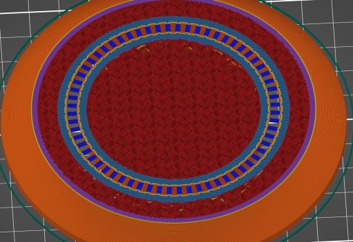
If this new model is sliced, the slicer produces a pattern, as shown in the next image.
As long as the bridged areas are small enough to consist just of perimeters, a perfect pattern of the shortest possible bridges is generated.
The next layer is the bridging layer which looks like it was generated before, but this time it is printed on top of all these small bridges that prevent any problematic cases.
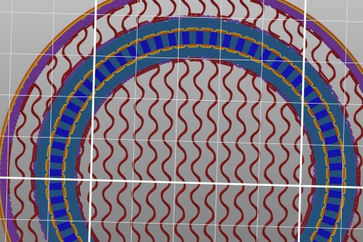
In the image above, you see the view from below, how the bridges are well-defined and only cover very short distances.
Conclusion
I use this simple technique to improve and extend bridging areas, especially for prints with PETG and other filaments that do not bridge well. These simple additions create much cleaner prints and as they are deeply hidden in grooves, they have no negative impact on the look of a part.
I hope this explanation gave you a good idea of how you can further improve your 3D models for FFF. If you have questions, missed any information, or wish to provide feedback, add a comment below or send me a message.
Happy printing!
More Posts

Designing 3D-Printable Pots

New Additions to the Storage Box System


