
I designed a very modular 19th-century-style lantern. You can print it in its simplest form as a simple candlelight to put on a table or a shelf. By printing additional elements, you create a wonderful LED lantern with a stand that looks slightly like a street lamp.
In this post, I share details about my ideas behind the design and its modularity. If you are not interested in all the details, click the button below to jump directly to the Printables page, where you will find all downloads, print and assembly instructions.
I am glad you choose to read on. 😄
Showcase
I created a short video that showcases many aspects of the design.
The Lantern Design
The core part of this design is the lantern itself. It has four sides at a slight angle. Have a look at the following drawing that shows several important features of the design:

You probably first notice the outer dimensions of the lamp. They build a perfect cube with a side length of 100mm. I used this dimension as a pretty standard card box format exists with these inner dimensions. A printed lamp fits perfectly into one of these boxes requiring no padding materials.
By designing an 8mm thick frame, the inner dimensions with the 80mm wide foot part create a pleasing form that distracts from the initial cube form.
For practical reasons, the outer dimensions dictate the angle of the side panel, as I had modularity in mind. The well-defined dimensions of the upper and lower frame lead to a simpler design for attachments and add-ons.
Secure No-Glue Assembly
An important aspect of this design was assembling the lantern without glueing any parts together or using screws. I like to provide more side panel designs, so you can reuse the frame and easily disassemble and reassemble the lantern as often as you like.
Look at detail C on the drawing above. Each panel has a raised lip on all four sides. Two very thin lips on each side panel’s left and right side and two larger ones at the top and bottom edge. Detail C shows how the lower lip of the side panel interlocks with a groove of the bottom frame. I designed this interlocking profile to insert all four side panels easily, but they stay in place even if the bottom part is not inserted yet. It simplifies the assembly, as you have your hands free when you lock the bottom part into place.

The bottom frame has four strong hook profiles around the inner opening. It takes force to click the bottom piece into place, as all four hook profiles must bend slightly. This is important to prevent the bottom from accidentally coming loose when the lantern is carried around. Also, these hooks shall be able to hold a higher pulling force than the weight of the lantern itself. This allows the creation of simple stands printed as one single part.
The side panel is securely fastened as soon as the bottom part is locked to the bottom frame. A pulling force on the panels does not affect the locking mechanism. To remove the side panels, you have to remove the bottom part first and this requires a pushing force in the middle of the base area.

I designed the four columns between the side panels as a simple “c”-shape. Each side panel has a thin lip on its left and right edge. The columns slide over these lips and press the edges of the side panels together. That way, I have the functional aspect, creating a stable connection of the sides and an aesthetical aspect, as the columns prevent light from escaping through the small gap between the sides.
The last element is the top frame or lid. Have a look at detail B of the previous drawing. I designed the top frame profile to be easily slid over the top edges of all four side panels while creating a secure connection with the lantern. The inner side of the top frame is a rim at the same angle as the side panels. The upper lip of the side panel is first clamped between the hook and this rim, then pressed outwards into the correct position.

This design uses two spring forces: One of the hook profiles in the top frame and one by slightly bending the side panel until its lip is completely embedded. At the very last moment, the lip from the side panel and the hook from the frame lock at an almost 90-degree angle. Therefore removing the top frame from the lantern requires a higher force than pushing it into place.
Again, this design is important, preventing the part from accidentally coming loose if the lantern is carried around being held at the top frame only.
The Artwork on the Side Panels
Anton Firsik created the artwork for the side panels. It is a forest scene with trees in the autumn.
The lantern column becomes the tree trunk, building an arc of branches over each side. The leaves of the trees have turned red, and some are falling to the ground, surrounding a different forest animal on each side.
When used with a candle, the holes for the leaves and the animals’ shapes cast a wonderful pattern to the wall behind the lantern. The video demonstrates this effect very well. Jump in the video to position 1:00, where you can see how the head of the dear appears in the background.
Mixing Colours with Various Thicknesses
To make printing the panel accessible to most people, the panel is not a multicolour print but a print with colour changes. Therefore transparent layers are printed on top of each other.


I already collected experience printing side panels like this when I designed my first version of a winter lamp (see project 1, project 2, project 3):
- As the colours mix, shining through the layers on top of each other, it is always good to order the colours from light to dark. Also, opposite colours need a special technique (more on this later).
- It is better to print multiple thinner layers, as few larger ones. In larger layers, there are more small gaps between the lines. Also, multiple passes of layers at different angles create a more uniform look. For my design, I choose a 0.15mm layer height for the colours, switching back to 0.2mm layers for the opaque colour and frame.
- It takes at least four layers to make an opaque colour completely cover the transparent layers below. That is another reason why using thinner layers is better than larger ones.
There is a wide variety of transparent PETG filaments, yet the level of colours varies greatly. For this reason, I created several side panel variants where the thickness of individual colours varies.

It allows for varying the intensity of individual colours or even using the same colour and creating shades.
Getting Rid of Gaps at the Perimeters
One problem with printing a side panel like this is the small gaps between the perimeter lines and the filled area.
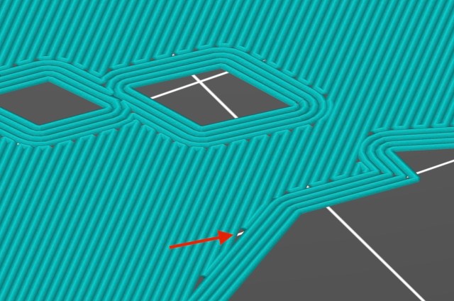
To solve this problem, I print four perimeters at the first layer to move these gaps inside the filled area.
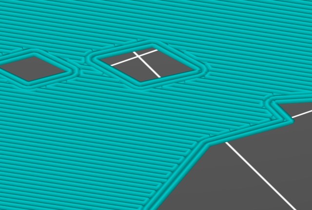
Starting from the next layer, I reduce the number of perimeters back to two. This simple trick creates a very clean shape with no light spills. For the design from Anton, I only had to do this for the first layer because opaque shapes surround all other colour areas. If the design has shades of colours in the same shape, I repeat this technique at the beginning of every new colour.
Separating Colours
To get closer to the artist’s original vision, I created a variant of the side panels that use bridging to separate the sky from the leaves’ colours.

This side panel variant has an embedded diamond pattern printed with a single line of filament:
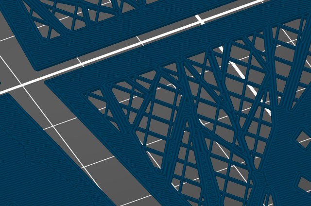
The pattern creates a structure that the first leaf colour can be securely printed on top of it. If the side panels had been printed with PLA, it would most likely work without this additional support, yet PETG does not bridge well, and there are only two additional layers printed on top.

Because the structure consists of single lines of filament, it has almost no effect on the light colour. Therefore, the filaments printed on top glow in lucid colours.
The pattern is visible at the front as a very light shade. So I am looking forward to doing more experiments with designs that incorporate a more complex layering of colours.

The Look
While all internal locking mechanisms are designed to make the lantern modular, I had more freedom to design the actual look of the frames and columns.

One of Anton’s specialities is creating these incredibly lively artworks using straight lines. I chose to match the look of the lantern to his style and designed all features in a way with flat faces that create the illusion of roundings and curves.
The Lid Design
The lantern is perfect for candlelight on a table or shelf in its open form. To give the lantern a more lantern-like look, I designed a lid that replaces the top frame element. If the lantern is used with an LED light, the closed top adds to the aesthetics and moves the viewer’s focus to the illuminated side panels.

I chose a classical bead and cove profile with a fillet for the lid, as this overall shape resembles a form that was popular around the 18th century in Europe. Looking at the drawing above, the bead and the cove profile are constructed from a quarter of a circle. Yet, I used straight lines to stay true to the overall look of the lantern.

I removed as much material as possible inside the lid to allow a print without supports. As the 45º angle on the inside matches the angles on the outside, the lids also stack well. This is a side effect, though.
The Stand Design
When I designed the stand for the lantern, I had two goals: First, it shall match the overall look of the lantern in a way that the lantern looks like one piece, no matter if it is used with or without the stand. Second, the stand shall succeed the modularity of the lantern, allowing it to change lengths and replace single elements of the stand with custom ones.

With the stand in its standard configuration, the lantern has a height of 33.6cm. I found this is a good compromise to build an object that can function as a decorative lamp that looks nice but does not dominate a room. It was also the minimum height to give the lantern a street-light look.
Elements of the Stand
The stand replaces the bottom part of the lantern with a stand adapter. The adapter is a short cylinder with three grooves to attach other elements.
From there, two column elements are attached. A supporting base plate is inserted directly under the base of the lantern, and two decorative elements are mounted between the two columns.
The most prominent part is the foot which has the same side lengths as the lantern itself. It has a pedestal that gives a smooth transition from the foot platform to the column of the lamp.
The Lantern Adapter
The most complex part of the stand is the lantern adapter.

This adapter serves two purposes: First, it provides a secure way to attach the lantern to the columns of the stand, and second, it provides attachment points to install an LED light and a diffusor.
The Locking Mechanism
The same locking mechanism is repeated at all connection points to make the whole stand as modular as possible.

In the drawing above, you can see a cut through the stand’s column. The stand is hollow to save material and allow a cable to be routed through it.

The drawing above illustrates why there are three grooves at each adapter. These three grooves allow each adapter to lock at three different positions, depending on how many elements are mounted between the two parts.
While the two parts mounted between the two column elements are merely decorative, the platform inserted directly below the lantern’s base serves an important purpose. Any force put on the frame is transferred to the top rim of the column. Without this platform, the column would press against the locks between the stand adapter and the lower frame, which would be undesirable.
The Look
Like the lamp, the stand follows the lantern style with flat surfaces and straight lines.

A decorative knot in the upper third of the column gives a little bit of this 19th-century aesthetic without compromising the hard corners and linear design.

The column itself copies the rough shape of the lantern, with four bars that give it somewhat of a square profile.

The platform directly below the lantern part is used to prevent forces on the locking mechanism of the adapter in the lower frame but also soften the shape of the lantern, matching the form of the lid on top.
Conclusion
Even though this lantern looks complex, I prepared all parts to guarantee an easy and pleasant print. It is a rewarding weekend print (starting Friday evening), and the modularity of the lantern allows you to reprint and replace individual parts as you like.
You will find all files and detailed print instructions on the Printable page of the project:
I made this lantern modular because I already have plans for additional extensions and variations. There will be new side panel artwork, instructions, an adapter for USB-powered LED light, and maybe parts in a completely different style. All these new parts will be compatible, and you can print and replace individual parts without needing to reprint the whole lamp.
I hope you enjoyed all these details and this lantern design. As I stopped doing social media posts, if you like my work and this project, please share it or write about it. It will help other people find this design. But no worries, my projects and posts will never be based on or influenced by likes, links and popularity. 😄
And as always, if you have questions, missed any information, or wish to provide feedback, add a comment below or send me a message.
Happy printing!
Photo Gallery


More Posts

Designing 3D-Printable Pots

New Version 2 of the Pattern Generator
